KiCad Nightly Reference Manual
Авторские права
This document is Copyright The KiCad Documentation Contributors. You may distribute it and/or modify it under the terms of either the GNU General Public License (http://www.gnu.org/licenses/gpl.html), version 3 or later, or the Creative Commons Attribution License (http://creativecommons.org/licenses/by/3.0/), version 3.0 or later.
All trademarks within this guide belong to their legitimate owners.
Соавторы
Jean-Pierre Charras, Graham Keeth
Перевод
KiCad Russian Team
alex9, 2016
Барановский Константин <[email protected]>, 2019
Обратная связь
The KiCad project welcomes feedback, bug reports, and suggestions related to the software or its documentation. For more information on how to submit feedback or report an issue, please see the instructions at https://www.kicad.org/help/report-an-issue/
Software and Documentation Version
This user manual is based on KiCad 10.99. Functionality and appearance may be different in other versions of KiCad.
Documentation revision: 2e473680.
Introduction to the KiCad Drawing Sheet Editor
The Drawing Sheet Editor is a tool to create custom drawing sheets for use in the KiCad Schematic and Board Editors. Drawing sheets can include custom title blocks, frames, logos, as well as other text and graphics.
The frame, title block, and other graphic items (logos) are collectively called a drawing sheet.
Basic drawing sheet items are:
-
Line (линии)
-
Rectangle (прямоугольники)
-
Text (with keywords that will be replaced by the actual text, like the date, page number…) in the Schematic or Board Editors.
-
Poly (полигоны; в основном – для размещения логотипов и специальных графических фигур)
-
Bitmap (растровые изображения)
| Растровые изображения могут быть начерчены только в некоторых форматах (только в PDF и PS). Таким образом, для других форматов будет начерчен только ограничивающий прямоугольник. |
-
Items can be repeated, and text and poly_polygons can be rotated.
Drawing Sheet Editor files
The Drawing Sheet Editor reads and writes KiCad drawing sheet files (.kicad_wks). These files can be used as custom drawing sheets for schematic and PCB designs by selecting a custom drawing sheet in the Page Setup dialog in each editor.
When the Drawing Sheet Editor is first opened, it displays the default KiCad drawing sheet is used until a different drawing sheet file is opened.
Основные понятия
Basic drawing sheet item properties
Basic drawing sheet items are:
-
Line (линии)
-
Rectangle (прямоугольники)
-
Text (with keywords, with will be replaced by the actual text, like the date, page number…) in the Schematic or PCB Editors.
-
Poly-polygons (mainly to place logos and special graphic shapes). These poly polygons are created by the Image Converter tool, and cannot be built inside the Drawing Sheet Editor, because it is not possible to create such shapes by hand.
-
Bitmap (растровые изображения) – для размещения логотипов.
| Растровые изображения могут быть начерчены только в некоторых форматах – PDF и PS. |
При этом:
-
Text, poly-polygons and bitmaps are defined by a position, and can be rotated.
-
Line (линии, а на самом деле – отрезки) and Rectangle (прямоугольники) определяются двумя точками: начальной и конечной. Они не могут быть повернуты (для отрезков это бесполезно).
Эти основные элементы могут быть повторены.
Repeated text also accepts an increment value for labels (has meaning only if the text is one letter or one digit).
Определение координат
Each position, start point and end point of items is always relative to a page corner. This feature allows you to define a drawing sheet which is not dependent on the paper size.
Базовые углы и координаты.

-
Когда меняется размер страницы, положение элемента относительно его базового угла не меняется.
-
Обычно основные надписи привязаны к правом нижнем углу, поэтому при создании элемента по умолчанию задаётся именно этот угол.
Для каждой из двух точек, определяющих прямоугольник или линию, задаётся свой базовый угол.
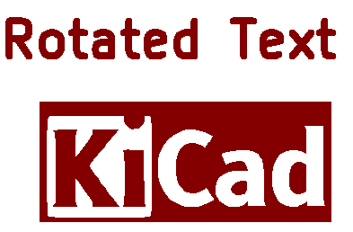
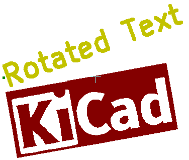
Поворот
Items which have a position defined by just one point (text and poly-polygons) can be rotated:
Нормально: Поворот = 0
Повёрнуто: Поворот = 20 и 10 градусов
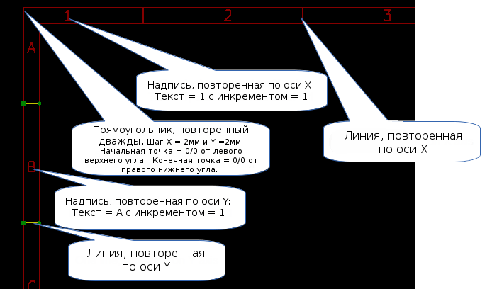
Повтор
Элементы могут быть повторены.
Это полезно для создания сетки и меток.
Text and keywords
Keywords
Text can be simple strings or can include keywords.
Keywords are replaced by actual values when the drawing sheet is used in a schematic or PCB design. They behave like text variables in the Schematic and Board Editors, except the values are either automatically set by the editor or set by the user in the Page Setup dialog of the respective editor.
The keyword syntax is ${KEYWORD}. The keyword, including the surrounding ${}, will be replaced by the keyword’s value.
| Keyword name | Description |
|---|---|
|
Version number of KiCad. |
|
Sheet number. |
|
Total number of sheets. |
|
Contents of the |
|
Contents of the |
|
Filename of the schematic or PCB design file, with a file extension. |
|
Contents of the |
|
Name of the current PCB layer. This is blank in the Schematic and Board Editors. It is only shown in plots of PCB designs. |
|
Current sheet’s paper size, which is set in Page Setup. |
|
Contents of the |
|
Sheet name of the current sheet. This is blank in the Board Editor. |
|
Sheet path of the current sheet. This is blank in the Board Editor. |
|
Contents of the |
For example, Size: ${PAPER} displays "Size: A4" when the paper size is set to A4.
When the Preview display mode is active (![]() ), the title block is displayed like in the Schematic and PCB Editors, with keywords replaced with the corresponding values. You can configure the displayed values in the Page Preview Settings dialog (
), the title block is displayed like in the Schematic and PCB Editors, with keywords replaced with the corresponding values. You can configure the displayed values in the Page Preview Settings dialog (![]() ).
).
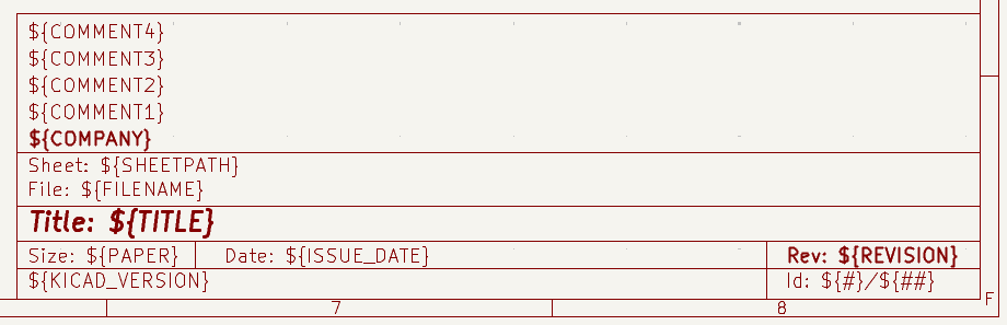
When the Edit mode is active (![]() ), the title block is displayed without replacing keywords.
), the title block is displayed without replacing keywords.
Multi-line text
Text can be multi-line.
There are 2 ways to insert a new line in text:
-
Insert the
\n2 chars sequence (mainly in Page setup dialog in KiCad). -
Insert a new line in the Drawing Sheet Editor Design window.
Вот пример второго способа:
Настройка
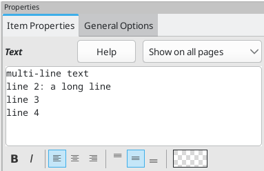
Вывод
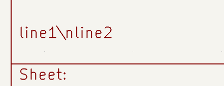
Multi-line text in Page Setup dialog
In the Page Setup dialog, text controls do not accept multi-line text.
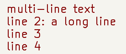
The \n 2 character sequence should be inserted to force a new line inside a text object.
Here is a two line text object, in the Comment2 field:

Результат:
However, if you really want the \n inside the text, enter \\n.

и получите:
Ограничения
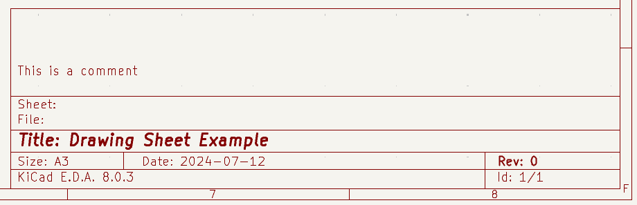
Ограничение первого листа
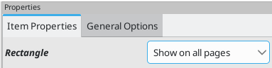
When using the Schematic Editor, the full schematic often uses more than one page.
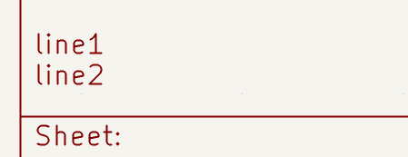
Usually drawing sheet items are shown on all pages, but you can also set each item to be shown only on the first page or on all pages except the first page. To change which pages an item is shown on, use the dropdown in the the item’s Item Properties panel. Options are show on all pages, first page only, and subsequent pages only.
Text maximum size constraint
Text items have a maximum size constraint. You can set a maximum height and maximum width, which together form a bounding box defining the maximum size of the text object.
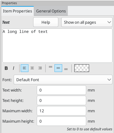
If the text object is bigger than the maximum size in a given dimension, the text object will be dynamically compressed in that dimension in order to fit within the bounding box. This will result in the text being visually distorted. If the text fits within the bounding box, the text will not be compressed.
When either parameter is set to 0, KiCad will not enforce a maximum size in that dimension.
Some text with the maximum height and width set to 0:
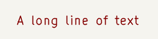
The same text compressed because the maximum width is set smaller than the width of the text:
Invoking the Drawing Sheet Editor
The Drawing Sheet Editor is typically invoked from a command line, or from the KiCad Project Manager.
Синтаксис коммандной строки: pl_editor <*.kicad_wks file to open>
Drawing Sheet Editor Commands
Главное окно
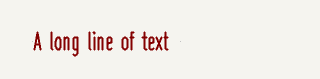
The image below shows the main window of the Drawing Sheet Editor.
The main part of the screen is the editing canvas for the open drawing sheet.
The right pane is a properties editor for editing the selected item. It only appears when an item is selected in the canvas.
Панель инструментов главного окна
Верхняя панель инструментов обеспечивает легкий доступ к следующим командам:
|
Create a new drawing sheet. |
|
Load a drawing sheet file. |
|
Save the current drawing sheet in a |
|
Display the page size selector and the title block user data editor. |
|
Prints the current page. |
|
Undo/redo tools. |
|
Zoom in, out, redraw and auto, respectively. |
|
Show the drawing sheet in Preview mode: text is shown like in the Schematic or PCB Editors, with text keywords replaced by user text. |
|
Show the drawing sheet in Edit mode: text is displayed "as is", without any keyword replacement. |
|
Reference corner selection, for coordinates displayed to the status bar. |
|
Selection of the page number (page & or other pages). This selection has meaning only if some items than have a page option, are not shown on all pages (in a schematic for instance, which contains more than one page). |
Команды рабочей области
Клавиатурные команды
F1 |
Zoom In |
F2 |
Zoom Out |
F3 |
Refresh Display |
F4 |
Move cursor to center of display window |
Home |
Fit footprint into display window |
Space Bar |
Set relative coordinates to the current cursor position |
Right Arrow |
Move cursor right one grid position |
Left Arrow |
Move cursor left one grid position |
Up Arrow |
Move cursor up one grid position |
Down Arrow |
Move cursor down one grid position |
Команды мыши
Scroll Wheel |
Zoom in and out at the current cursor position |
Ctrl + Scroll Wheel |
Pan right and left |
Shift + Scroll Wheel |
Pan up and down |
Right Button Click |
Open context menu |
Контекстное меню
Отображается по щелчку правой кнопкой мыши:
-
Добавить линию
-
Добавить прямоугольник
-
Добавить надпись
-
Add Bitmap
-
Выбор масштаба: непосредственный выбор масштаба отображения.
-
Выбор сетки: непосредственный выбор сетки.
Строка состояния
The status bar is located at the bottom of the Drawing Sheet Editor and provides useful information to the user.

Coordinates are always relative to the corner selected as the reference corner in the reference corner dropdown in the menubar.
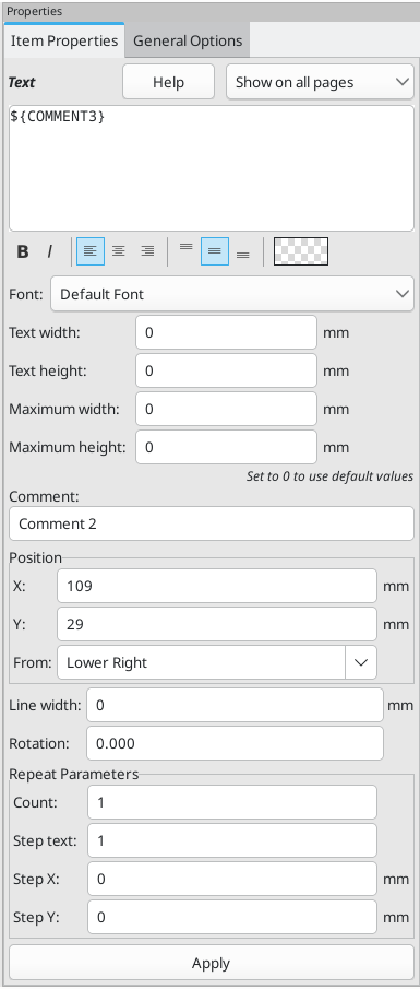
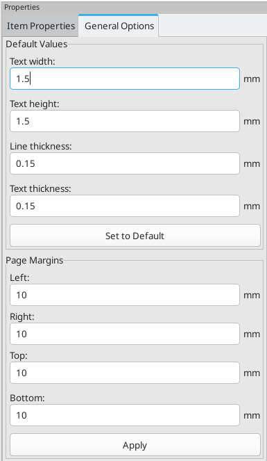
Properties editor
The right pane is a properties editor. It only appears when an item is selected in the canvas. The Item Properties tab contains properties for the selected item. These properties depend on what type of item is selected. The General Options tab lets you edit default properties and margins for the *sheet.
Changes made in the properties editor are not applied until you click the Apply button.
|
|
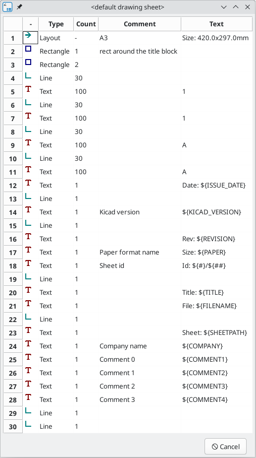
Design Inspector window
The Design Inspector shows a table of every item in the drawing sheet and their properties. Selecting an item in the Design Inspector also selects the item on the canvas and leaves it selected when you close the Design Inspector.
To open the Design Inspector, use Inspect → Show Design Inspector.
Interactive editing
Выбор элемента
Элемент может быть выбран:
-
From the Design Inspector
-
щелчком на нём левой кнопкой мыши.
-
щелчком на нём правой кнопкой мыши (будет выведено всплывающее меню).
When selected, this item is drawn in a lighter shade of color and the properties editor will be displayed for the selected item.
When right clicking on the item, a pop-up menu is displayed. The pop menu contents depend on the type of object selected.
Создание элемента
To add a new item, use the appropriate button in the right toolbar and then click on the canvas. The item will be added to the canvas and selected, and the properties editor for the new item will open. You can edit the item’s properties in the properties editor, then click Apply to modify the new item.
The available items are lines (![]() ), rectangles (
), rectangles (![]() ), text (
), text (![]() ), and bitmaps (
), and bitmaps (![]() ).
).
You can also add new items from the right-click context menu.
Logos must first be created by the Image Converter tool, which creates a page layout description file. You can use the Append Existing Drawing Sheet command to insert the logo (a poly polygon) contained in the new drawing sheet.
Adding lines, rectangles and text
When you add lines, rectangles, or text, the item will be added to the canvas, selected, and shown in the properties editor. You can edit the item’s properties in the properties editor, then click Apply to apply the changes.
You can also move the item in the canvas after it has been placed by dragging it or using the Move command (kbd:[M]). Lines and rectangles can be moved as a shape, but you can also move their points individually.
Lines and rectangles typically use the same corner reference for both the start and end points. If this is not the case, the item’s geometry will change when the sheet size or margins are changed.
Добавление логотипов
To add a logo, a poly polygon (the vectored image of the logo) must be first created using the Image Converter tool, which is available in the main KiCad Project Manager window. Polygons cannot be created by hand.
The Image Converter tool creates a drawing sheet file which contains only one item: a poly polygon representing the source image. This drawing sheet file is appended to the current design, using the Append Existing Drawing Sheet command.
| This command can be used to append any drawing sheet file, regardless of what items it contains. All items in the appended file will be added to the current design. |
После того, как полигон вставлен, он может быть перемещен, а его параметры – отредактированы.
Добавление растровых изображений
You can add an image bitmap using many common bitmap formats (PNG, JPEG, BMP, etc.).
-
После импорта растрового изображения его разрешение – 300 PPI (пикселей на дюйм).
-
This value can be modified in the properties editor.
-
The actual size of the bitmap in the drawing sheet depends on this parameter.
-
Be aware that using higher definition values brings larger output files, and can have an effect on draw or plot time.
Bitmaps can be repeated but not rotated.