KiCad Nightly Referenzhandbuch
Copyright
This document is Copyright The KiCad Documentation Contributors. You may distribute it and/or modify it under the terms of either the GNU General Public License (http://www.gnu.org/licenses/gpl.html), version 3 or later, or the Creative Commons Attribution License (http://creativecommons.org/licenses/by/3.0/), version 3.0 or later.
All trademarks within this guide belong to their legitimate owners.
Mitwirkende
Jean-Pierre Charras, Graham Keeth
Übersetzung
Lorenz Bewig <[email protected]>, 2025; Carsten Schönert <[email protected]>, 2016
Feedback
Das KiCad-Projekt freut sich über Rückmeldungen, Fehlerberichte und Vorschläge in Bezug auf die Software oder ihre Dokumentation. Weitere Informationen zum Einreichen von Feedback oder zum Melden eines Problems finden Sie in den Anweisungen unter https://www.kicad.org/help/report-an-issue/
Version der Software und Dokumentation
Dieses Benutzerhandbuch basiert auf KiCad 10.99. Funktionalität und Aussehen können sich in anderen Versionen von KiCad unterscheiden.
Revision der Dokumentation: 2e473680.
Einführung in den KiCad-Zeichnungsblatteditor
Der Zeichnungsblatteditor ist ein Werkzeug zum Erstellen von benutzerdefinierten Zeichnungsblättern zur Verwendung in den KiCad-Schaltplan- und Leiterplatteneditoren. Zeichnungsblätter können benutzerdefinierte Titelblöcke, Rahmen, Logos sowie andere Texte und Grafiken enthalten.
Der Rahmen, das Schriftfeld und andere grafische Elemente (Logos) werden zusammen als Zeichnungsblatt bezeichnet.
Grundlegende Zeichnungsblattelemente sind:
-
Linien
-
Rechtecke
-
Text (mit Schlüsselwörtern, die durch den eigentlichen Text ersetzt werden, wie z.B. das Datum, die Seitenzahl…) im Schaltplan- oder Leiterplatteneditor.
-
Multipolygone (hauptsächlich zum Platzieren von Logos und speziellen grafischen Formen)
-
Bitmap Grafiken.
| Bitmaps können nur von wenigen Plottern geplottet werden (nur PDF und PS). Daher wird bei anderen Plottern nur ein Begrenzungsrahmen geplottet. |
-
Elemente können wiederholt werden, und Text und Polygone können gedreht werden.
Zeichnungsblatteditor-Dateien
Der Zeichnungsblatteditor liest und schreibt KiCad-Zeichnungsblattdateien (.kicad_wks). Diese Dateien können als benutzerdefinierte Zeichenblätter für Schaltplan- und Leiterplattenentwürfe verwendet werden, indem ein benutzerdefiniertes Zeichenblatt im Dialogfeld Seite einrichten in jedem Editor ausgewählt wird.
Wenn der Zeichnungsblatteditor zum ersten Mal geöffnet wird, zeigt er das Standard-KiCad-Zeichnungsblatt an, bis eine andere Zeichnungsblattdatei geöffnet wird.
Ablaufplan
Grundlegende Eigenschaften von Zeichnungsblattelementen
Grundlegende Zeichnungsblattelemente sind:
-
Linien
-
Rechtecke
-
Text (mit Schlüsselwörtern, die durch den tatsächlichen Text ersetzt werden, wie z.B. das Datum, die Seitenzahl…) im Schaltplan- oder PCB-Editor.
-
Multipolygone (hauptsächlich zum Platzieren von Logos und speziellen grafischen Formen). Diese Polygone werden mit dem Werkzeug Bildumwandler erstellt und können nicht im Zeichnungsblatteditor erstellt werden, da es nicht möglich ist, derartige Formen von Hand zu erstellen.
-
Bitmap Grafiken zur Platzierung von Logos.
| Bitmap Grafiken können nur von einigen Plottern gezeichnet werden: nur PDF und PS. |
Zusammengefasst:
-
Texte, Multipolygone und Bitmap Grafiken werden durch eine Position definiert und können gedreht werden.
-
Linien (tatsächlich Segmente) und Rechtecke werden durch zwei Punkte definiert: einen Startpunkt und einen Endpunkt. Sie können nicht gedreht werden (was für Segmente auch nutzlos wäre).
Diese Basisemente können wiederholt werden.
Wiederholter Text erlaubt auch einen Inkrementwert für Beschriftungen (hat nur Bedeutung, wenn der Text aus einem Buchstaben oder einer Ziffer besteht).
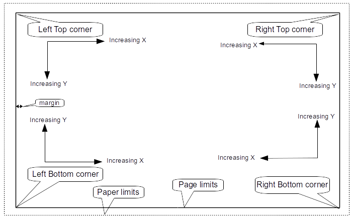
Koordinaten-Definition
Jede Position, jeder Startpunkt und jeder Endpunkt von Elementen ist immer relativ zu einer Seitenecke. Mit dieser Funktion können Sie ein Zeichnungsblatt definieren, das nicht vom Papierformat abhängig ist.
Referenzpunkte und Koordinaten:
-
Wenn die Seitengröße geändert wird, ändert sich die Position des Elements relativ zu seiner Referenzecke nicht.
-
Normalerweise werden Titelblöcke in der rechten unteren Ecke angebracht, daher ist diese Ecke die Standardecke beim Erstellen eines Elements.
Bei Rechtecken und Segmenten, die zwei definierte Punkte haben, hat jeder Punkt seine Referenzecke.
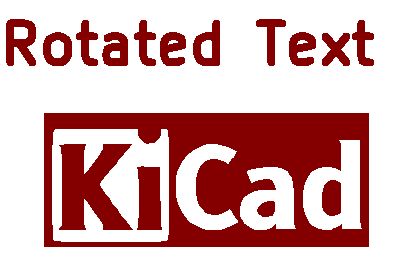
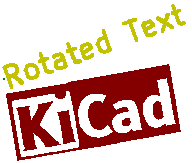
Rotation
Elemente, deren Position durch nur einen Punkt definiert ist (Text und Polygone), können gedreht werden:
Normal: Rotation = 0
Gedreht: Rotation = 20 und 10 Grad.
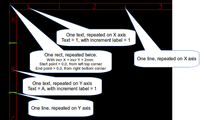
Wiederholungsoption
Elemente können wiederholt werden:
Dies ist nützlich, um Raster und Rasterbeschriftungen zu erstellen.
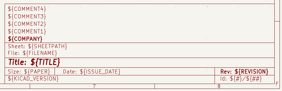
Text und Schlüsselwörter
Schlüsselwörter
Text kann aus einfachen Zeichenfolgen bestehen oder Schlüsselwörter enthalten.
Schlüsselwörter werden durch konkrete Werte ersetzt, wenn das Zeichnungsblatt in einem Schaltplan oder PCB-Design verwendet wird. Sie verhalten sich wie Textvariablen in den Schaltplan- und Platineneditoren, mit dem Unterschied, dass die Werte entweder automatisch vom Editor oder vom Benutzer im Dialogfeld „Seite einrichten“ des jeweiligen Editors festgelegt werden.
Die Syntax für Schlüsselwörter lautet ${KEYWORD}. Das Schlüsselwort, einschließlich der umgebenden ${}, wird durch den Wert des Schlüsselworts ersetzt.
| Keyword name | Description |
|---|---|
|
Version number of KiCad. |
|
Sheet number. |
|
Total number of sheets. |
|
Contents of the |
|
Contents of the |
|
Filename of the schematic or PCB design file, with a file extension. |
|
Contents of the |
|
Name of the current PCB layer. This is blank in the Schematic and Board Editors. It is only shown in plots of PCB designs. |
|
Current sheet’s paper size, which is set in Page Setup. |
|
Contents of the |
|
Sheet name of the current sheet. This is blank in the Board Editor. |
|
Sheet path of the current sheet. This is blank in the Board Editor. |
|
Contents of the |
Beispielsweise wird bei Größe: ${PAPER} „Größe: A4“ angezeigt, wenn das Papierformat auf A4 eingestellt ist.
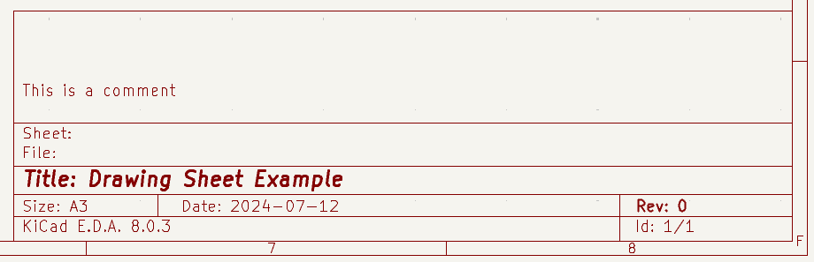
Wenn der Vorschaumodus aktiv ist ( ![]() ), wird der Titelblock wie im Schaltplan- und Platineneditor angezeigt, wobei Schlüsselwörter durch die entsprechenden Werte ersetzt werden. Sie können die angezeigten Werte im Dialogfeld „Seitenvorschau-Einstellungen“ konfigurieren (
), wird der Titelblock wie im Schaltplan- und Platineneditor angezeigt, wobei Schlüsselwörter durch die entsprechenden Werte ersetzt werden. Sie können die angezeigten Werte im Dialogfeld „Seitenvorschau-Einstellungen“ konfigurieren (![]() ).
).
Wenn der Bearbeitungsmodus aktiv ist (![]() ), wird der Titelblock ohne Ersetzen der Schlüsselwörter angezeigt.
), wird der Titelblock ohne Ersetzen der Schlüsselwörter angezeigt.
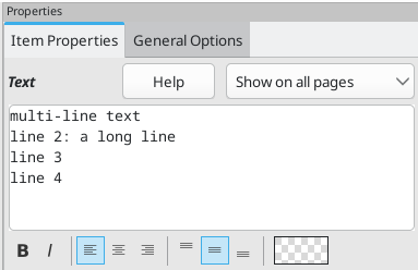
Mehrzeiliger Text
Text kann mehrzeilig sein.
Es gibt zwei Möglichkeiten, eine neue Zeile in einen Text einzufügen:
-
Fügen Sie die Zeichenfolge
\nein (hauptsächlich im Dialogfeld „Seiteneinstellungen“ in KiCad). -
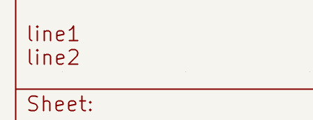
Fügen Sie eine neue Zeile im Designfenster vom Zeichenblatteditor hinzu.
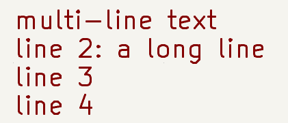
Hier ist ein Beispiel:
Einrichtung
Ausgabe
Mehrzeiliger Text im Dialog 'Seiteneinstellungen'
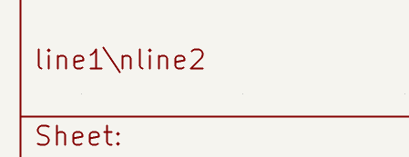
Im Dialog 'Seiteneinstellungen' akzeptieren Textsteuerelemente keinen mehrzeiligen Text.
Die Zeichenfolge \n sollte eingefügt werden, um einen Zeilenumbruch innerhalb eines Textobjekts zu bewirken.
Hier ist ein zweizeiliges Textobjekt im Feld 'Kommentar2':

Hier ist der eigentliche Text:
Wenn Sie jedoch tatsächlich das Zeichen \n innerhalb des Textes benötigen, geben Sie \\n ein.

Und der angezeigte Text:
Einschränkungen
Einschränkung auf Seite 1
Bei der Arbeit mit dem Schaltplaneditor umfasst der vollständige Schaltplan oft mehr als eine Seite.
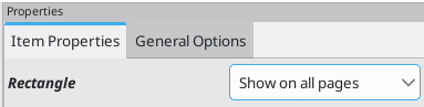
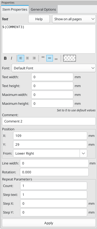
Normalerweise werden Zeichnungsblattelemente auf allen Seiten angezeigt, aber Sie können auch festlegen, dass jedes Element nur auf der ersten Seite oder auf allen Seiten außer der ersten Seite angezeigt wird. Um zu ändern, auf welchen Seiten ein Element angezeigt wird, verwenden Sie das Dropdown-Menü im Bereich Elementeigenschaften des Elements. Die Optionen sind: Auf allen Seiten anzeigen, Nur auf der ersten Seite und Nur auf den folgenden Seiten.
Maximale Textgröße
Textelemente haben eine maximale Größenvorgabe. Sie können eine maximale Höhe und eine maximale Breite festlegen, die zusammen einen Begrenzungsrahmen bilden, der die maximale Größe des Textobjekts definiert.
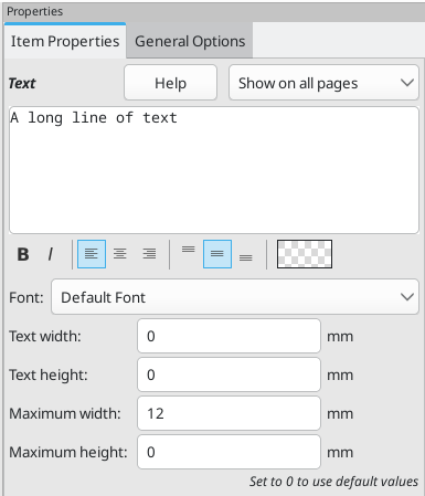
Wenn das Textobjekt größer als die maximale Größe in einer bestimmten Dimension ist, wird das Textobjekt in dieser Dimension dynamisch gestaucht, damit es in den Begrenzungsrahmen passt. Dies führt zu einer optischen Verzerrung des Textes. Wenn der Text in den Begrenzungsrahmen passt, wird er nicht gestaucht.
Wenn einer der beiden Parameter auf 0 gesetzt ist, erzwingt KiCad keine maximale Größe in dieser Dimension.
Ein Text, dessen maximale Höhe und Breite auf 0 gesetzt sind:
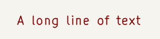
Der gleiche Text komprimiert, da die maximale Breite kleiner als die Breite des Textes gesetzt ist:

Aufrufen des Zeichnungsblatteditors
Der Zeichnungsblatt-Editor wird in der Regel über eine Befehlszeile oder über den KiCad-Projektmanager aufgerufen.
In der Befehlszeile lautet die Syntax pl_editor <*.kicad_wks-Datei>.
Befehle des Zeichnungsblatteditors
Hauptfenster
Das Bild unten zeigt das Hauptfenster des Zeichnungsblatteditors.
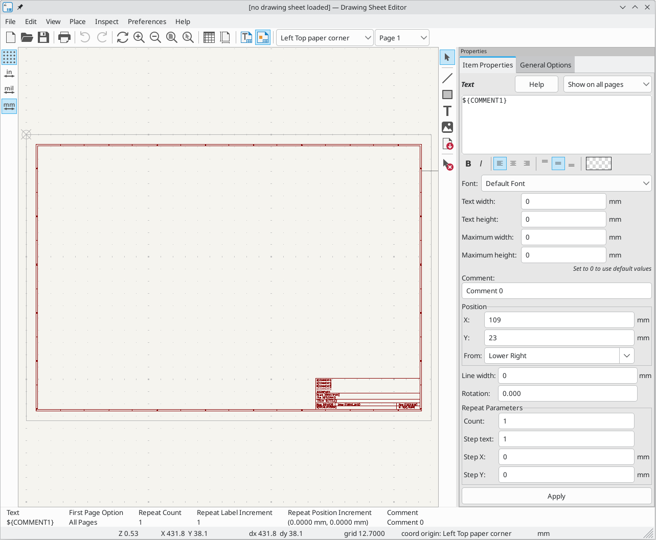
Der Hauptteil des Bildschirms ist die Bearbeitungsfläche für das geöffnete Zeichenblatt.
Der rechte Bereich ist ein Eigenschafteneditor zum Bearbeiten des ausgewählten Elements. Er wird nur angezeigt, wenn ein Element im Arbeitsbereich ausgewählt ist.
Symbolleiste des Hauptfensters
Die obere Symbolleiste ermöglicht einen einfachen Zugriff auf die folgenden Befehle:
|
Create a new drawing sheet. |
|
Load a drawing sheet file. |
|
Save the current drawing sheet in a |
|
Display the page size selector and the title block user data editor. |
|
Prints the current page. |
|
Undo/redo tools. |
|
Zoom in, out, redraw and auto, respectively. |
|
Show the drawing sheet in Preview mode: text is shown like in the Schematic or PCB Editors, with text keywords replaced by user text. |
|
Show the drawing sheet in Edit mode: text is displayed "as is", without any keyword replacement. |
|
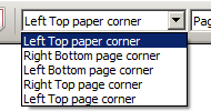
Reference corner selection, for coordinates displayed to the status bar. |
|
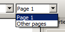
Selection of the page number (page & or other pages). This selection has meaning only if some items than have a page option, are not shown on all pages (in a schematic for instance, which contains more than one page). |
Befehle im Zeichnungsbereich
Tastaturbefehle
F1 |
Zoom In |
F2 |
Zoom Out |
F3 |
Refresh Display |
F4 |
Move cursor to center of display window |
Home |
Fit footprint into display window |
Space Bar |
Set relative coordinates to the current cursor position |
Right Arrow |
Move cursor right one grid position |
Left Arrow |
Move cursor left one grid position |
Up Arrow |
Move cursor up one grid position |
Down Arrow |
Move cursor down one grid position |
Mauskommandos
Scroll Wheel |
Zoom in and out at the current cursor position |
Ctrl + Scroll Wheel |
Pan right and left |
Shift + Scroll Wheel |
Pan up and down |
Right Button Click |
Open context menu |
Kontextmenü
Anzeige durch rechten Mausklick:
-
Linie hinzufügen
-
Rechteck hinzufügen
-
Text hinzufügen
-
Bitmap hinzufügen
-
Zoomauswahl: direkte Auswahl der Zoomstufe.
-
Rasterauswahl: direkte Auswahl des Rasters.
Informationen in der Statusleiste
Die Statusleiste befindet sich am unteren Rand des Zeichnungsblatteditors und liefert dem Benutzer hilfreiche Informationen.

Die Koordinaten beziehen sich immer auf die Ecke, die in der Menüleiste über das Dropdown-Menü als Referenzecke ausgewählt wurde.
Eigenschaften-Editor
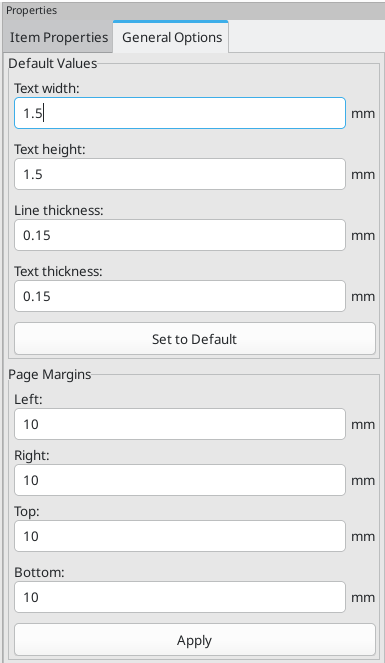
Der rechte Bereich ist ein Eigenschafteneditor. Er wird nur angezeigt, wenn ein Element im Arbeitsbereich ausgewählt ist. Die Registerkarte Elementeigenschaften enthält Eigenschaften für das ausgewählte Element. Diese Eigenschaften hängen davon ab, welcher Elementtyp ausgewählt ist. Auf der Registerkarte Allgemeine Optionen können Sie die Standardeigenschaften und Ränder für das Blatt festlegen.
Änderungen, die im Eigenschafteneditor vorgenommen werden, werden erst nach Klicken auf die Schaltfläche Anwenden übernommen.
|
|
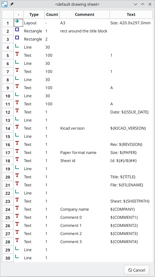
Design-Inspektor-Fenster
Der Design-Inspektor enthält eine Tabelle mit allen Elementen des Zeichnungsblatts und deren Eigenschaften. Wenn Sie ein Element im Design-Inspektor auswählen, wird dieses Element auch auf der Arbeitsfläche ausgewählt und bleibt ausgewählt, wenn Sie den Design-Inspektor schließen.
Um den Design-Inspektor zu öffnen, wählen Sie im Menü Inspektion → Design-Inspektor anzeigen.
Interaktive Bearbeitung
Elementauswahl
Ein Element kann folgendermaßen ausgewählt werden:
-
Vom Design-Inspektor
-
Durch einen Linksklick.
-
Durch einen Rechtsklick (ein Kontextmenü wird angezeigt).
Wenn es ausgewählt ist, wird dieses Element in einer helleren Farbe dargestellt und der Eigenschafteneditor für das ausgewählte Element angezeigt.
Durch einen Rechtsklick auf das Element wird ein Kontextmenü angezeigt. Der Inhalt des Kontextmenüs hängt vom Typ des ausgewählten Objekts ab.
Erstellen von Elementen
Um ein neues Element hinzuzufügen, verwenden Sie die entsprechende Schaltfläche in der rechten Symbolleiste und klicken Sie dann auf die Arbeitsfläche. Das Element wird zur Arbeitsfläche hinzugefügt und ausgewählt, und der Eigenschafteneditor für das neue Element wird geöffnet. Sie können die Eigenschaften des Elements im Eigenschafteneditor bearbeiten und dann auf Anwenden klicken, um das neue Element zu ändern.
Die verfügbaren Elemente sind Linien (![]() ), Rechtecke (
), Rechtecke (![]() ), Text (
), Text (![]() ) und Bitmaps (
) und Bitmaps (![]() ).
).
Sie können auch über das Kontextmenü der rechten Maustaste neue Elemente hinzufügen.
Logos müssen zunächst mit dem Bildumwandler erstellt werden, der eine Beschreibungsdatei für das Seitenlayout erstellt. Mit dem Befehl Bestehendes Zeichnungsblatt hinzufügen können Sie das Logo (ein Multipolygon) in das neue Zeichnungsblatt einfügen.
Linien, Rechtecke und Text hinzufügen
Wenn Sie Linien, Rechtecke oder Text hinzufügen, wird das Element zur Arbeitsfläche hinzugefügt, ausgewählt und im Eigenschafteneditor angezeigt. Sie können die Eigenschaften des Elements im Eigenschafteneditor bearbeiten und dann auf Anwenden klicken, um die Änderungen zu übernehmen.
Sie können das Element auch nach dem Platzieren auf der Arbeitsfläche verschieben, indem Sie es ziehen oder den Befehl „Verschieben“ (kbd:[M]) verwenden. Linien und Rechtecke können als Form verschoben werden, Sie können jedoch auch ihre Punkte einzeln verschieben.
Linien und Rechtecke verwenden in der Regel dieselbe Eckreferenz für den Start- und Endpunkt. Ist dies nicht der Fall, ändert sich die Geometrie des Elements, wenn die Blattgröße oder die Ränder geändert werden.
Logos hinzufügen
Um ein Logo hinzuzufügen, muss zunächst mit dem Bildumwandler, der im Hauptfenster des KiCad-Projektmanagers verfügbar ist, ein Multipolygon (die Vektorgrafik des Logos) erstellt werden. Polygone können nicht von Hand erstellt werden.
Der Bildumwandler erstellt eine Zeichnungsblattdatei, die nur ein Element enthält: ein Polygon, das das Quellbild darstellt. Diese Zeichnungsblattdatei wird mit dem Befehl „Bestehendes Zeichnungsblatt hinzufügen“ an das aktuelle Design angehängt.
| Mit diesem Befehl können Sie jede beliebige Zeichnungsdatei anhängen, unabhängig davon, welche Elemente sie enthält. Alle Elemente in der angehängten Datei werden zum aktuellen Entwurf hinzugefügt. |
Sobald ein Multipolygon eingefügt wurde, kann es verschoben und seine Parameter bearbeitet werden.
Bitmaps hinzufügen
Sie können eine Bitmap-Grafik in vielen gängigen Bitmap-Formaten (PNG, JPEG, BMP usw.) hinzufügen.
-
Beim Importieren einer Bitmap-Grafik wird ihre Auflösung auf 300 PPI (Pixel pro Zoll) festgelegt.
-
Dieser Wert kann im Eigenschafteneditor geändert werden.
-
Die tatsächliche Größe der Bitmap im Zeichnungsblatt hängt von diesem Parameter ab.
-
Beachten Sie, dass die Verwendung höherer Auflösungswerte zu größeren Ausgabedateien führt und sich auf die Zeichnungs- oder Plotzeit auswirken kann.
Bitmaps können vervielfältigt, aber nicht gedreht werden.