Manual de referència
Copyright
This document is Copyright © 2010-2018 by its contributors as listed below. You may distribute it and/or modify it under the terms of either the GNU General Public License (http://www.gnu.org/licenses/gpl.html), version 3 or later, or the Creative Commons Attribution License (http://creativecommons.org/licenses/by/3.0/), version 3.0 or later.
Totes les marques comercials citades en aquesta guia pertanyen als seus propietaris legítims.
Contribuïdors
Jean-Pierre Charras, Fabrizio Tappero.
Traducció
Robert Antoni Buj Gelonch <[email protected]>, 2016
Realimentació
Si us plau, adreceu aquí els vostres informes d’errors de programari, suggeriments o per a noves versions:
-
Quant a la documentació de KiCad: https://gitlab.com/kicad/services/kicad-doc/issues
-
Quant al programari de KiCad: https://gitlab.com/kicad/code/kicad/issues
-
About KiCad translation: https://gitlab.com/kicad/code/kicad-i18n/issues
Data de publicació i versió del programari
2015, May 21.
Introducció
KiCad
KiCad és una eina de programari de codi obert per a la creació de diagrames d’esquemes electrònics i plaques de circuits impresos. Sota la seva aparença singular, KiCad incorpora un recull elegant de les següents eines de programari:
-
KiCad: Project manager
-
Eeschema: Schematic editor and component editor
-
Pcbnew: Circuit board layout editor and footprint editor
-
GerbView: Gerber viewer
3 utility tools are also included:
-
Bitmap2Component: Component maker for logos. It creates a schematic component or a footprint from a bitmap picture.
-
PcbCalculator: A calculator that is helpful to calculate components for regulators, track width versus current, transmission lines, etc.
-
Pl Editor: Page layout editor.
Aquestes eines generalment s’executen des del gestor del projecte, però també es poden executar com a eines independents.
KiCad no presenta cap limitació quan a la mida de la placa, pot gestionar fins a 32 capes de coure, 14 capes tècniques i 4 capes auxiliars.
KiCad can create all the files necessary for building printed circuit boards, including:
-
Fitxers Gerber per als foto-plòters
-
fitxers de perforació
-
fitxers d’ubicació de components
En ser codi obert (amb llicència GPL), KiCad representa l’eina ideal per als projectes orientats a la creació de maquinari electrònic amb un gust de codi obert.
KiCad is available for Linux, Windows and Apple macOS.
Fitxers i directoris de KiCad
KiCad crea i utilitza els fitxers (i els directoris) amb les següents extensions específiques de fitxers per a l’edició d’esquemes i de plaques.
Ficher del gestor del projecte:
*.pro |
Fitxer de mida reduïda que conté alguns paràmetres per al projecte actual, incloent-hi la llista de biblioteques de components. |
Fitxers de l’editor d’esquemes:
*.sch |
Schematic files, which do not contain the components themselves. |
*.lib |
Schematic component library files, containing the component descriptions: graphic shape, pins, fields. |
*.dcm |
Schematic component library documentation, containing some component descriptions: comments, keywords, reference to data sheets. |
*_cache.lib |
Schematic component library cache file, containing a copy of the components used in the schematic project. |
sym-lib-table |
Symbol library list (symbol library table): list of symbol libraries available in the schematic editor. |
Fitxers i directoris de l’editor de plaques:
*.kicad_pcb |
Board file containing all info but the page layout. |
*.pretty |
Footprint library folders. The folder itself is the library. |
*.kicad_mod |
Footprint files, containing one footprint description each. |
*.brd |
Board file in the legacy format. Can be read, but not written, by the current board editor. |
*.mod |
Footprint library in the legacy format. Can be read by the footprint or the board editor, but not written. |
fp-lib-table |
Footprint library list (footprint library table): list of footprint libraries (various formats) which are loaded by the board or the footprint editor or CvPcb. |
Fitxers comuns
*.kicad_wks |
Page layout description files, for people who want a worksheet with a custom look. |
*.net |
Netlist file created by the schematic, and read by the board editor. This file is associated to the .cmp file, for users who prefer a separate file for the component/footprint association. |
Fitxers especials
*.cmp |
Association between components used in the schematic and their footprints. It can be created by Pcbnew and imported by Eeschema. Its purpose is to import changes from Pcbnew to Eeschema, for users who change footprints inside Pcbnew (for instance using Exchange Footprints command) and want to import these changes in schematic. |
Altres fitxers:
Es generen amb KiCad per a la fabricació o la documentació.
*.gbr |
Gerber files, for fabrication. |
*.drl |
Drill files (Excellon format), for fabrication. |
*.pos |
Position files (ASCII format), for automatic insertion machines. |
*.rpt |
Report files (ASCII format), for documentation. |
*.ps |
Plot files (Postscript), for documentation. |
Plot files (PDF format), for documentation. |
|
*.svg |
Plot files (SVG format), for documentation. |
*.dxf |
Plot files (DXF format), for documentation. |
*.plt |
Plot files (HPGL format), for documentation. |
Instal·lació i configuració
Opcions de visualització
Hardware accelerated renderer in Pcbnew and Gerbview requires video card with support of OpenGL v2.1 or higher.
Instal·lació de la configuració predeterminada
The default configuration file named kicad.pro is supplied in kicad/template. It serves as a template for any new project and is used to set the list of library files loaded by Eeschema. A few other parameters for Pcbnew (default text size, default line thickness, etc.) are also stored here.
Another default configuration file named fp-lib-table may exist. It will be used only once to create a footprint library list; otherwise the list will be created from scratch.
Modifying the default configuration
The default kicad.pro file can be freely modified, if desired.
Verifiqueu que tingueu accés d’escriptura a kicad/template/kicad.pro
Run KiCad and load kicad.pro project.
Run Eeschema via KiCad manager. Modify and update the Eeschema configuration, to set the list of libraries you want to use each time you create new projects.
Run Pcbnew via KiCad manager. Modify and update the Pcbnew configuration, especially the footprint library list. Pcbnew will create or update a library list file called footprint library table. There are 2 library list files (named fp-lib-table): The first (located in the user home directory) is global for all projects and the second (located in the project directory) is optional and specific to the project.
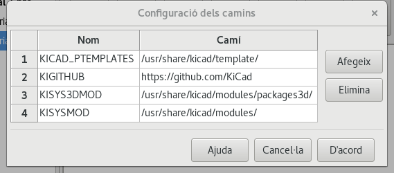
Paths configuration
In KiCad, one can define paths using an environment variable. A few environment variables are internally defined by KiCad, and can be used to define paths for libraries, 3D shapes, etc.
This is useful when absolute paths are not known or are subject to change (e.g. when you transfer a project to a different computer), and also when one base path is shared by many similar items. Consider the following which may be installed in varying locations:
-
Eeschema component libraries
-
Pcbnew footprint libraries
-
3D shape files used in footprint definitions
For instance, the path to the connect.pretty footprint library, when using the KISYSMOD environment variable, would be defined as ${KISYSMOD}/connect.pretty
This option allows you to define a path using an environment variable, and add your own environment variables to define personal paths, if needed.
KiCad environment variables:
KICAD_PTEMPLATES |
Templates used during project creation (DEPRECATED as of version 5.0.0-rc2, use KICAD_TEMPLATE_DIR instead). If you are using this variable, it must be defined. |
KICAD_SYMBOL_DIR |
Base path of symbol library files. |
KIGITHUB |
Frequently used in example footprint lib tables. If you are using this variable, it must be defined. |
KISYS3DMOD |
Base path of 3D shapes files, and must be defined because an absolute path is not usually used. |
KISYSMOD |
Base path of footprint library folders, and must be defined if an absolute path is not used in footprint library names. |
KICAD_TEMPLATE_DIR |
Location of templates installed with KiCad. |
KICAD_USER_TEMPLATE_DIR |
Location of personal templates. |
Note also the environment variable KIPRJMOD is always internally defined by KiCad, and is the current project absolute path.
For instance, ${KIPRJMOD}/connect.pretty is always the connect.pretty folder (the pretty footprint library) found inside the current project folder.
If you modify the configuration of paths, please quit and restart KiCad to avoid any issues in path handling.
Initialization of external utilities
You may define your favorite text editor and PDF viewer. These settings are used whenever you want to open a text or PDF file.
These settings are accessible from the Preference menu:
Selection of text editor
Before using a text editor to browse/edit files in the current project, you must choose the text editor you want to use.
Select Preferences → Set Text Editor to set the text editor you want to use.
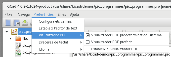
Selection of PDF viewer
You may use the default PDF viewer or choose your own.
To change from the default PDF viewer use Preferences → PDF Viewer → Set PDF Viewer to choose the PDF viewer program, then select Preferences → PDF Viewer → Favourite PDF Viewer.
On Linux the default PDF viewer is known to be fragile, so selecting your own PDF viewer is recommended.
Creating a new project
In order to manage a KiCad project consisting of schematic files, printed circuit board files, supplementary libraries, manufacturing files for photo-tracing, drilling and automatic component placement files, it is recommended to create a project as follows:
-
Creació d’un directori de treball per al projecte (amb KiCad o de qualsevol altra manera).
-
En aquest directori, utilitzeu KiCad per a crear un fitxer de projecte (el fitxer amb l’extensió .pro) a través de les icones «Crea un nou projecte» o «Crea un nou projecte des d’una plantilla».
| Use a unique directory for each KiCad project. Do not combine multiple projects into a single directory. |
KiCad creates a file with a .pro extension that maintains a number of parameters for project management (such as the list of libraries used in the schematic). Default names of both main schematic file and printed circuit board file are derived from the name of the project. Thus, if a project called example.pro was created in a directory called example, the default files will be created:
example.pro |
Project management file. |
example.sch |
Main schematic file. |
example.kicad_pcb |
Printed circuit board file. |
example.net |
Netlist file. |
example.* |
Various files created by the other utility programs. |
example-cache.lib |
Library file automatically created and used by the schematic editor containing a backup of the components used in the schematic. |
Importing a foreign project
KiCad is able to import files created using other software packages. Currently only Eagle 6.x or newer (XML format) is supported.
To import a foreign project, you need to select either a schematic or a board file in the import file browser dialog. Imported schematic and board files should have the same base file name (e.g. project.sch and project.brd). Once the requested files are selected, you will be asked to select a directory to store the imported files, which are going to be saved as a KiCad project.
Using KiCad project manager
KiCad project manager (kicad or kicad.exe) is a tool which can easily run the other tools (schematic and PCB editors, Gerber viewer and utility tools) when creating a design.
L’execució de les altres eines des del gestor KiCad té alguns avantatges:
-
Proves creuades entre l’editor d’esquemàtics i l’editor de plaques.
-
Proves creuades entre l’editor d’esquemàtics i el selector d’empremtes (CvPcb).
However, you can only edit the current project files. When these tools are run in stand alone mode, you can open any file in any project but cross probing between tools can give strange results.
Project manager window
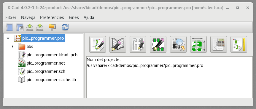
La finestra principal de KiCad es compon d’una vista en arbre del projecte, un panell de llançament que conté els botons que s’utilitzen per executar les diverses eines de programari, i una finestra de missatges. El menú i la barra d’eines es poden utilitzar per a crear, llegir i desar els fitxers del projecte.
Panell per llançar les utilitats
KiCad allows you to run all standalone software tools that come with it.
El panell de llançament està format pels 8 botons de sota que corresponen a les següents ordres (d'1 a 8, d’esquerra a dreta):
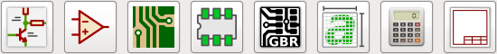
1 |
Eeschema |
Schematic editor. |
2 |
LibEdit |
Component editor and component library manager. |
3 |
Pcbnew |
Board layout editor. |
4 |
FootprintEditor |
Footprint editor and footprint library manager. |
5 |
Gerbview |
Gerber file viewer. It can also display drill files. |
6 |
Bitmap2component |
Tool to build a footprint or a component from a B&W bitmap image to create logos. |
7 |
Pcb Calculator |
Tool to calculate track widths, and many other things. |
8 |
Pl Editor |
Page layout editor, to create/customize frame references. |
Vista en arbre del projecte
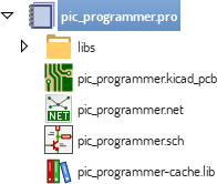
Double-clicking on the schematic file runs the schematic editor, in this case opening the file pic_programmer.sch.
Double-clicking on the board file runs the layout editor, in this case opening the file pic_programmer.kicad_pcb.
En fer clic dret en qualsevol dels fitxers a l’arbre del projecte permet la manipulació genèrica del fitxer.
Barra d’eines superior

KiCad top toolbar allows for some basic file operations:
|
Create a new project. If the default template file (kicad.pro) is found in kicad/template, it is copied into the working directory. |
|
Create a new project from an existing template. |
|
Open an existing project. |
|
Update and save the current project tree. |
|
Create a zip archive of the whole project. This includes schematic files, libraries, PCB, etc. |
|
Refresh the tree view, sometimes needed after a tree change. |
Project templates
Using a project template facilitates setting up a new project with predefined settings. Templates may contain pre-defined board outlines, connector positions, schematic elements, design rules, etc. Complete schematics and/or PCBs used as seed files for the new project may even be included.
Ús de plantilles
The File → New Project → New Project from Template menu will open the Project Template Selector dialog:
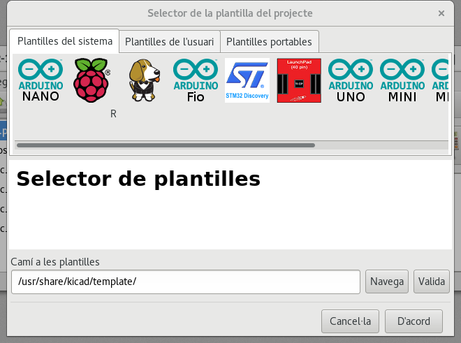
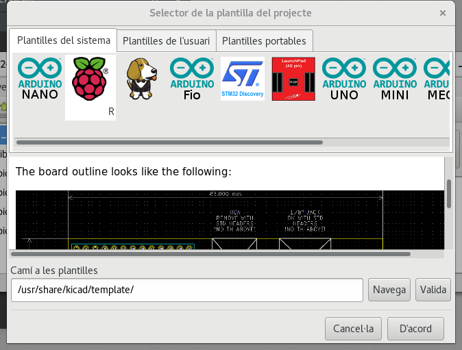
A single click on a template’s icon will display the template information, and a further click on the OK button creates the new project. The template files will be copied to the new project location and renamed to reflect the new project’s name.
Després de seleccionar una plantilla:
Template Locations:
KiCad looks for template files in the following paths:
-
path defined in the environment variable KICAD_USER_TEMPLATE_DIR
-
path defined in the environment variable KICAD_TEMPLATE_DIR
-
System templates: <kicad bin dir>/../share/kicad/template/
-
User templates:
-
Unix: ~/kicad/templates/
-
Windows: C:\Documents and Settings\username\My Documents\kicad\templates
-
Mac: ~/Documents/kicad/templates/
-
-
When the environment variable KICAD_PTEMPLATES is defined there is a third tab, Portable Templates, which lists templates found at the KICAD_PTEMPLATES path (DEPRECATED).
Creating templates
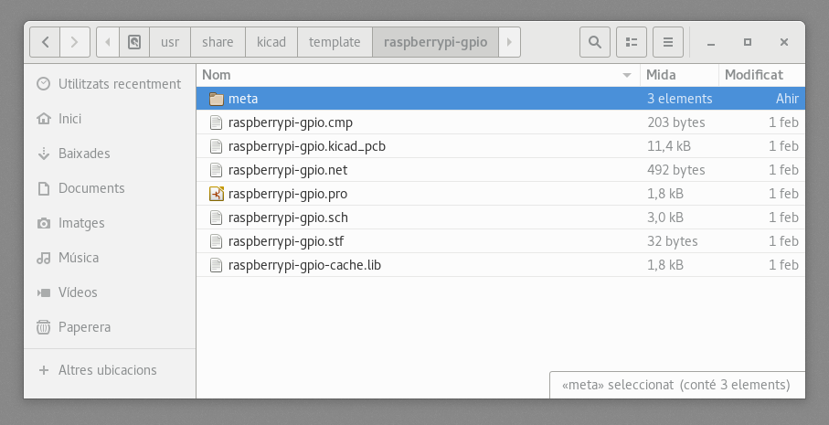
The template name is the directory name where the template files are stored. The metadata directory is a subdirectory named meta containing files describing the template.
All files and directories in a template are copied to the new project path when a project is created using a template, except meta.
When a new project is created from a template, all files and directories starting with the template name will be renamed with the new project file name, excluding the file extension.
The metadata consists of one required file, and may contain optional files. All files must be created by the user using a text editor or previous KiCad project files, and placed into the required directory structure.
Here is an example showing project files for raspberrypi-gpio template:
And the metadata files:
Required File:
meta/info.html |
HTML-formatted information describing the template. |
The <title> tag determines the actual name of the template that is exposed to the user for template selection. Note that the project template name will be cut off if it’s too long. Due to font kerning, typically 7 or 8 characters can be displayed.
Using HTML means that images can be easily in-lined without having to invent a new scheme. Only basic HTML tags can be used in this document.
Here is a sample info.html file:
<!DOCTYPE HTML PUBLIC "-//W3C//DTD HTML 4.0 Transitional//EN">
<HTML>
<HEAD>
<META HTTP-EQUIV="CONTENT-TYPE" CONTENT="text/html;
charset=windows-1252">
<TITLE>Raspberry Pi - Expansion Board</TITLE>
</HEAD>
<BODY LANG="fr-FR" DIR="LTR">
<P>This project template is the basis of an expansion board for the
<A HREF="http://www.raspberrypi.org/" TARGET="blank">Raspberry Pi $25
ARM board.</A> <BR><BR>This base project includes a PCB edge defined
as the same size as the Raspberry-Pi PCB with the connectors placed
correctly to align the two boards. All IO present on the Raspberry-Pi
board is connected to the project through the 0.1" expansion
headers. <BR><BR>The board outline looks like the following:
</P>
<P><IMG SRC="brd.png" NAME="brd" ALIGN=BOTTOM WIDTH=680 HEIGHT=378
BORDER=0><BR><BR><BR><BR>
</P>
<P>(c)2012 Brian Sidebotham<BR>(c)2012 KiCad Developers</P>
</BODY>
</HTML>Fitxers opcionals:
meta/icon.png |
A 64 x 64 pixel PNG icon file which is used as a clickable icon in the template selection dialog. |
Any other image files used by meta/info.html, such as the image of the board file in the dialog above, are placed in this folder as well.
Upgrading from Version 4 to Version 5
Changes were made to the behavior to KiCad during the version 5 development that can impact projects created with older versions of KiCad. This section serves as a guide to ensure the smoothest possible path when upgrading to version 5 of KiCad.
Schematic Symbol Libraries
Schematic symbol libraries are no longer accessed using a symbol (referred to as components in version 4) look up list. Symbol libraries are now managed by a symbol library table that behaves similarly to the footprint library table. This change is a significant improvement, but some schematics may need manual intervention when being converted to version 5.
In previous versions, KiCad used a list of library files to search when locating symbols in the Eeschema file. When locating a symbol, each path would be searched and the first library that held the symbol name would be used.
From v5, KiCad symbol names are prefixed with a nickname, and a lookup table matching nicknames to library paths is used to locate the library which holds the symbol. The table is called the 'symbol library table' and built from configuration files stored in the user’s KiCad configuration directory and the currently loaded project directory.
To upgrade a KiCad project from v4 to v5, nicknames for all of the library files need to be created and then schematic symbol names need to be prefixed with the correct nickname.
Global Symbol Library Table.
Eeschema v5 will automatically create a global symbol table when first started. You will be given a chance to skip this and create your own global symbol table by hand. You only need to do this if don’t use KiCad symbol libraries at all. Otherwise it is easier to modify the automatically generated global symbol table.
| If you track the symbol library repository, changes made to the default global symbol library table are not tracked by KiCad. You will have to manually keep the global symbol library table up to date. |
Symbol Library Table Mapping
Automatic remapping of symbols will be executed whenever a schematic is opened that has not been remapped. There are a few steps you should take ahead of time in order for the remapping to be the most effective.
| If you have been using a development build of KiCad, copy the full default global symbol library table file (sym-lib-table) from the template folder installed with the KiCad libraries or from the KiCad library repo to your KiCad user configuration folder. This will replace the empty one (most likely) created by Eeschema. If you do not do this, you will most likely end up with a bunch of broken symbol links. |
|
Remapped schematics will not be compatible with older versions of KiCad. The Remap Symbols dialog will make a backup of your schematic files and you should do the same if you remap manually. |
-
If possible, keep version 4 of KiCad installed on your system unless you have never used any of the symbol libraries distributed with KiCad.
-
If you get warning about missing libraries when you start version 4 of Eeschema, make sure to fix the missing libraries if they contain symbols that are in the schematic before you attempt to remap your schematic. Otherwise, the correct symbol will not be found and you will end up with broken symbol links in your schematic. You can test this by left clicking on a symbol in the schematic and verifying that the symbol is not being loaded from the cache library. If a symbol is being loaded from the cache library, Eeschema cannot find your part in the system or project symbol libraries. If you need a cached part to be available to other projects on your system, you will need to integrate it into a system or project library manually.
-
If symbol recovery is required during the remapping process, do not dismiss it. Failure to recover symbols will result in broken symbol links or the wrong symbol being linked in the schematic.
-
During the remapping process, symbol libraries not found in the global symbol library table will be used to create a project specific symbol library table. You can move them manually to the global symbol library table if that is your preference.
-
For the most accurate remapping, create a project library by copying the project cache file (project-name-cache.lib) to a different file and add it to the top of the symbol library list. You must use a version of KiCad prior to the symbol library table implementation in order to do this.
|
Fixing broken remapping:
A tool has been provided to attempt to fix remapping issues. If there are missing symbol library links in a schematic, they can be fixed by opening the "Tools→Edit Symbol Library References…" menu entry and clicking on the "Map Orphans" button.
|
Remapping Search Order
When remapping symbols, KiCad proceeds in the following order to assign the library to a symbol:
-
Global Symbol Library Table: Symbols are preferentially mapped to the global symbol library table, if one exists.
-
Project specific libraries: Libraries listed in the project library list that are not in the global symbol library table are searched next.
-
Project cache file: If a symbol doesn’t exist in the listed libraries above, it is first rescued — a copy is made from the cache and placed in the proj-rescue.lib — before the symbol is mapped to this new, rescue library.
Symbol Names and Symbol Library Nickname Limitations
Symbol names may not contain <SPACE>, ':', '/'.
Library nicknames may not contain <SPACE>, ':'.
Existing symbol names with these characters must be renamed by manually editing the relevant schematic and library files.
Symbol Cache Library Availability
The cache library is no longer shown in either the symbol library viewer or the symbol library editor. The cache should never be edited because any changes are overwritten by the next schematic save.
Board File Format Changes
Several new features have been added to Pcbnew which impact the board file format. Using these new features in board designs will prevent them from being opened with previous versions of Pcbnew.
-
Rounded rectangle footprint pads.
-
Custom shape footprint pads.
-
Footprint pad names longer than four characters.
-
Keep out zones on more than a single layer.
-
3D models offset saved as millimeters instead of inches.
-
Footprint text locking.
Global Footprint Library Table.
If you track the footprint library repository, changes made to the default global footprint library table are not tracked by KiCad. You will have to manually keep the global footprint library table up to date.