リファレンス・マニュアル
著作権
This document is Copyright © 2019-2021 by its contributors as listed below. You may distribute it and/or modify it under the terms of either the GNU General Public License (http://www.gnu.org/licenses/gpl.html), version 3 or later, or the Creative Commons Attribution License (http://creativecommons.org/licenses/by/3.0/), version 3.0 or later.
貢献者
Heitor de Bittencourt. Mathias Neumann
翻訳
starfort <starfort AT nifty.com>, 2019.
フィードバック
The KiCad project welcomes feedback, bug reports, and suggestions related to the software or its documentation. For more information on how to sumbit feedback or report an issue, please see the instructions at https://www.kicad.org/help/report-an-issue/
はじめに
The KiCad PCB Calculator is a set of utilities to help you find the values of components or other parameters of a layout. The Calculator has the following tools:
-
レギュレーター
-
配線幅
-
導体間隔
-
伝送線路
-
RF アッテネーター
-
カラー コード
-
ボード クラス
レギュレーター
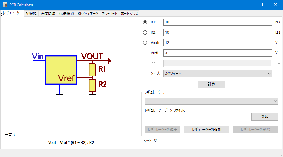
レギュレーター
この計算機は、リニア定電圧レギュレーターと低損失定電圧レギュレーターで使用される抵抗の値を見つけるのに役立ちます。
For the Standard Type, the output voltage Vout as a function of the reference voltage Vref and resistors R1 and R2 is given by:

For the 3 terminal type, there is a correction factor due to the quiescent current Iadj flowing from the adjust pin:

この電流は一般的に 100 uA 以下であり、気をつけながら無視することができます。
To use this calculator, enter the parameters of the regulator Type, Vref and, if needed, Iadj, select the field you want to calculate (one of the resistors or the output voltage) and enter the other two values.
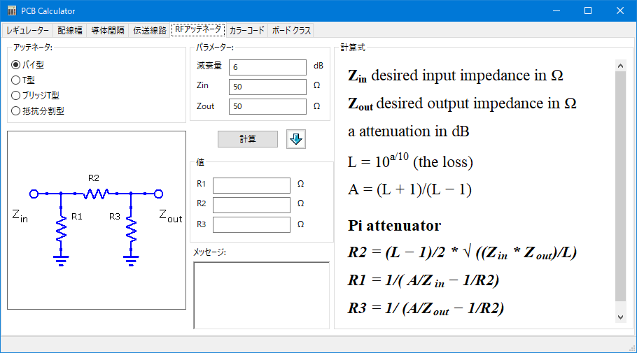
RF アッテネーター
With the RF Attenuator utility you can calculate the values of the resistors needed for different types of attenuators:
-
パイ型
-
T型
-
ブリッジ T 型
-
抵抗分割型
To use this tool, first select the type of attenuator you need, then enter the desired attenuation (in dB) and input/output impedances (in Ohms).
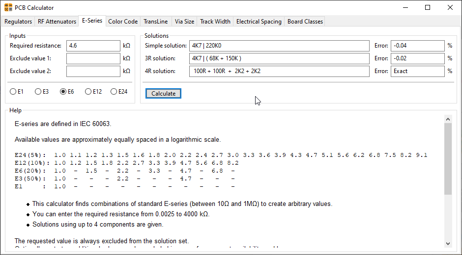
E-Series
This calculator helps to identify combinations of standard E-series resistors that meet a required resistance, optionally excluding several resistor values that are not available.
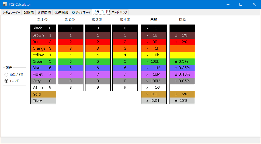
カラー コード
この計算機は、抵抗のカラー バーを抵抗値に翻訳するのを助けます。この機能を使うには、抵抗の 許容誤差 (10%、5% または 2% 以下) を最初に選択します。例えば:
-
黄 紫 赤 金: 4 7 x100 ±5% = 4700 Ω, 許容誤差 5%
-
1 kΩ, 許容誤差 1%: 茶 黒 黒 茶 茶
伝送線路
伝送線路理論は、高周波とマイクロ波工学の授業における基本です。
In the calculator you can choose different sorts of Line Types and their special parameters. The models implemented are frequency-dependent, so they disagree with simpler models at high enough frequencies.
This calculator is heavilly based on Transcalc.
The transmission line types and the reference of their mathematical models are listed below:
-
Microstrip line:
-
H. A. Atwater, “Simplified Design Equations for Microstrip Line Parameters”, Microwave Journal, pp. 109-115, November 1989.
-
-
Coplanar wave guide.
-
Coplanar wave guide with ground plane.
-
Rectangular waveguide:
-
S. Ramo, J. R. Whinnery and T. van Duzer, "Fields and Waves in Communication Electronics", Wiley-India, 2008, ISBN: 9788126515257.
-
-
Coaxial line.
-
Coupled microstrip line:
-
H. A. Atwater, “Simplified Design Equations for Microstrip Line Parameters”, Microwave Journal, pp. 109-115, November 1989.
-
M. Kirschning and R. H. Jansen, "Accurate Wide-Range Design Equations for the Frequency-Dependent Characteristic of Parallel Coupled Microstrip Lines," in IEEE Transactions on Microwave Theory and Techniques, vol. 32, no. 1, pp. 83-90, Jan. 1984. doi: 10.1109/TMTT.1984.1132616.
-
Rolf Jansen, "High-Speed Computation of Single and Coupled Microstrip Parameters Including Dispersion, High-Order Modes, Loss and Finite Strip Thickness", IEEE Trans. MTT, vol. 26, no. 2, pp. 75-82, Feb. 1978.
-
S. March, "Microstrip Packaging: Watch the Last Step", Microwaves, vol. 20, no. 13, pp. 83.94, Dec. 1981.
-
-
Stripline.
-
Twisted pair.
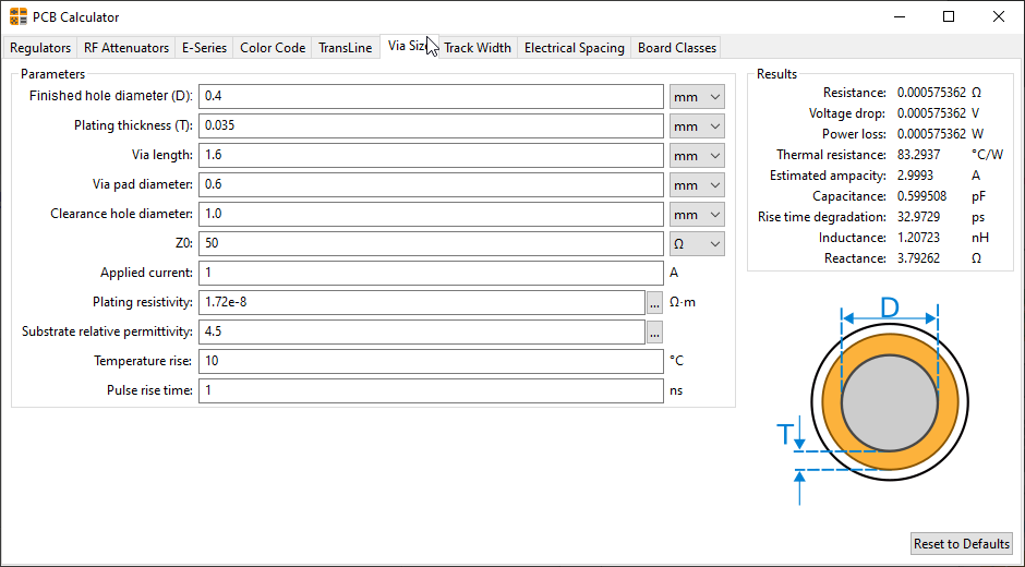
Via Size
The Via Size tool calculates the electrical and thermal properties of a given plated through-hole pad or via.
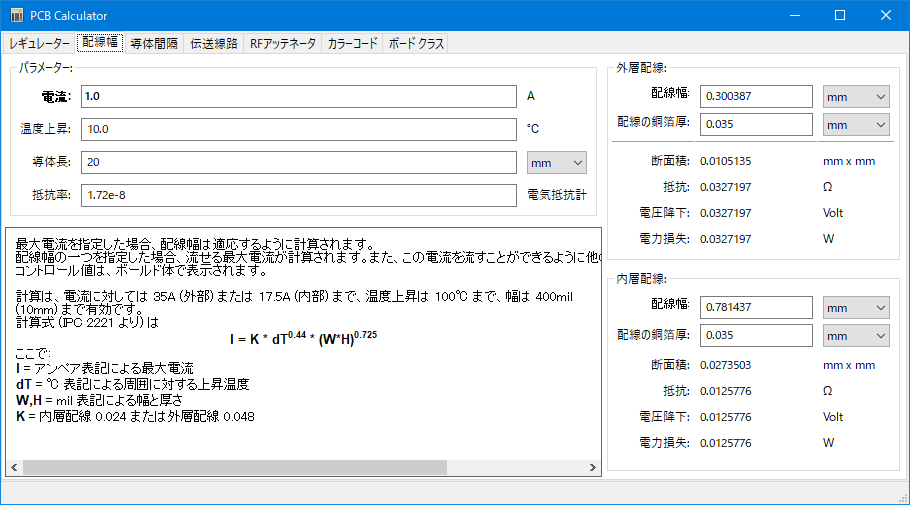
配線幅
The Track Width tool calculates the trace width for printed circuit board conductors for a given current and temperature rise. It uses formulas from IPC-2221 (formerly IPC-D-275).
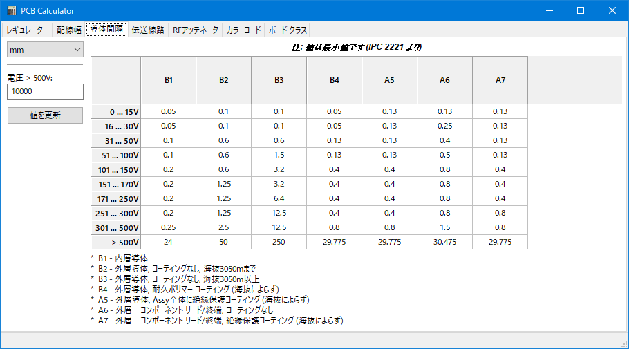
導体間隔
This table helps finding the minimum clearance between conductors.
Each line of the table has a minimum recomended distance between conductors for a given voltage (DC or AC peaks) range. If you need the values for voltages higher than 500V, enter the value in the box in the left corner and press Update Values.
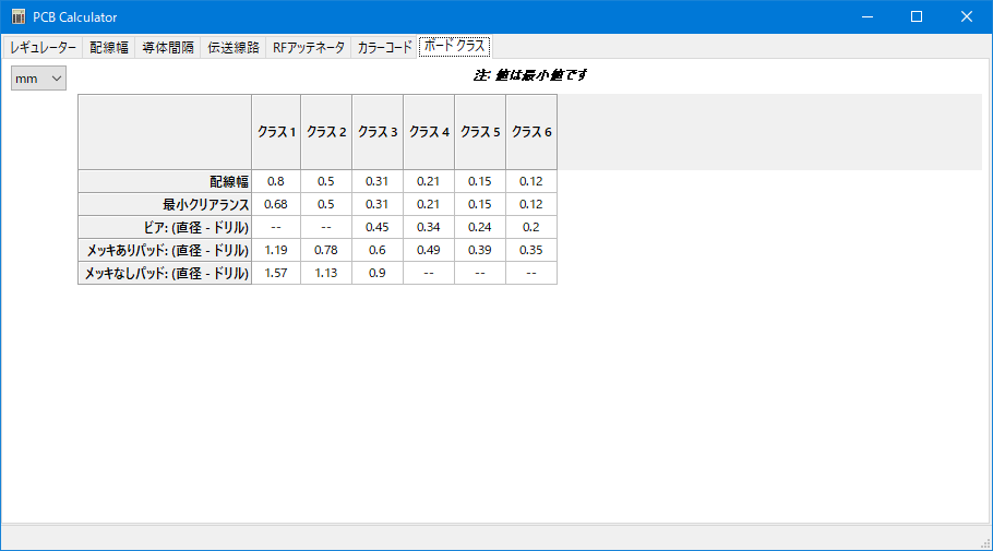
ボード クラス
Performance Classes
In IPC-6011 have been three performance classes established
-
Class 1 General Electronic Products: Includes consumer products, some computer and computer peripherals suitable for applications where cosmetic imperfections are not important and the major requirement is function of the completed printed board.
-
Class 2 Dedicated Service Electronic Products: Includes communications equipment, sophisticated business machines, instruments where high performance and extended life is required and for which uninterrupted service is desired but not critical. Certain cosmetic imperfections are allowed.
-
Class 3 High Reliability Electronic Products: Includes the equipment and products where continued performance or performance on demand is critical. Equipment downtime cannot be tolerated and must function when required suchas in life support items or flight control systems. Printed boards in this class are suitable for applications where high levels of assurance are required and service is essential.
PCB Types
In IPC-6012B there are also 6 Types of PCB defined:
-
Printed Boards without plated through holes (1)
-
1 Single-Sided Board
-
-
And Boards with plated through holes (2-6)
-
2 Double-Sided Board
-
3 Multilayer board without blind or buried vias
-
4 Multilayer board with blind and/or buried vias
-
5 Multilayer metal core board without blind orburied vias
-
6 Multilayer metal core board with blind and/orburied vias
-