Referenz Handbuch
Copyright
This document is Copyright © 2010-2018 by its contributors as listed below. You may distribute it and/or modify it under the terms of either the GNU General Public License (http://www.gnu.org/licenses/gpl.html), version 3 or later, or the Creative Commons Attribution License (http://creativecommons.org/licenses/by/3.0/), version 3.0 or later.
Alle Markenrechtsnamen in diesem Guide gehören den rechtmäßigen Eigentümern.
Mitwirkende
Jean-Pierre Charras, Fabrizio Tappero.
Übersetzung
André S. <[email protected]> 2015, Carsten Schoenert <[email protected]> 2016
Feedback
Bitte senden Sie alle Fehlermeldungen, Vorschläge oder neue Versionen an:
-
Zum KiCad-Dokument: https://gitlab.com/kicad/services/kicad-doc/issues
-
Zur KiCad-Software: https://gitlab.com/kicad/code/kicad/issues
-
About KiCad translation: https://gitlab.com/kicad/code/kicad-i18n/issues
Datum der Veröffentlichung und Softwareversion
Published on May 30, 2015.
Einleitung zu Eeschema
Beschreibung
Eeschema is a schematic capture software distributed as a part of KiCad and available under the following operating systems:
-
Linux
-
Apple macOS
-
Windows
Unabhängig vom Betriebssystem sind alle mit Eeschema erstellten Dateien 100% zwischen den Betriebssystemen kompatibel und austauschbar.
Eeschema ist eine integrierte Anwendung, alle Funktionen vom Zeichnen, Steuern, Layout, Bibliotheksmanagement und Zugriff auf die PCB-Design Software werden aus Eeschema heraus ausgeführt.
Eeschema is intended to cooperate with PcbNew, which is KiCad’s printed circuit design software. It can also export netlist files, which lists all the electrical connections, for other packages.
Eeschema includes a symbol library editor, which can create and edit symbols and manage libraries. It also integrates the following additional but essential functions needed for modern schematic capture software:
-
Prüfung der elektrischen Vorgaben durch einen Elektrischen Regel Check (ERC) für die automatische Prüfung auf falsche und fehlende Verbindungen.
-
Ausgabe von Plot-Dateien in vielen Formaten (Postscript, PDF, HPGL und SVG).
-
Bill of Materials generation (via Python or XSLT scripts, which allow many flexible formats).
Technischer Überblick
Eeschema is limited only by the available memory. There is thus no real limitation to the number of components, component pins, connections or sheets. In the case of multi-sheet diagrams, the representation is hierarchical.
Eeschema can use multi-sheet diagrams in a few ways:
-
Einfache Hierarchie (jede Schaltung wird nur einmal verwendet).
-
Komplexe Hierarchie (manche Schaltungen werden in mehreren Instanzen mehr als einmal verwendet).
-
Flache Hierarchie (Schaltpläne sind nicht explizit über den Hauptschaltplan verbunden).
Allgemeine Eeschema Befehle
Commands can be executed by:
-
Klicken auf die Menüleiste (oben am Bildschirm).
-
Klicken auf die Symbole oben im Fenster (allgemeine Befehle).
-
Klicken auf die Symbole auf der rechten Seite des Bildschirms (spezielle Befehle oder "Werkzeuge").
-
Klicken auf die Symbole auf der linken Seite am Bildschirm (Darstellungsoptionen).
-
Durch Betätigen von Maustasten (wichtige komplementäre Befehle). Ein Rechtsklick öffnet in der Regel ein Kontextmenü für das Element unter dem Cursor (Zoom, Raster und Bearbeitung des Elements).
-
Function keys (F1, F2, F3, F4, Insert and Space keys). Specifically: Escape key cancels the command in progress. Insert key allows the duplication of the last element created.
-
Pressing hot keys which typically perform a select tool command and begin tool action at the current cursor location. For a list of hot keys, see the "Help→List Hotkeys" menu entry or press 'Ctrl+F1' key.

Mausbefehle
Basisbefehle
Linke Taste
-
Single click: displays the characteristics of the symbol or text under the cursor in the status bar.
-
Double click: edit (if the element is editable) the symbol or text.
Rechte Taste
-
Öffnet ein Pop-Up Menü.
Block operations
Sie können in allen Eeschema Menüs markierte Gruppierungen bewegen, ziehen, kopieren und löschen.
Areas are selected by drawing a box around items using the left mouse button.
Holding Shift'', Ctrl'', or ``Shift + Ctrl'' during selection respectively performs copying, dragging and deletion:
Linke Maustaste |
Bewege Auswahl. |
Umschalt + linke Maustaste |
Kopiere Auswahl. |
Strg + linke Maustaste |
Ziehe Auswahl. |
Strg + Umschalt + linke Maustaste |
Lösche Auswahl. |
Während des Ziehens oder Kopierens können Sie:
-
Noch einmal klicken um die Elemente zu platzieren.
-
Click the right button or press Escape key to cancel.
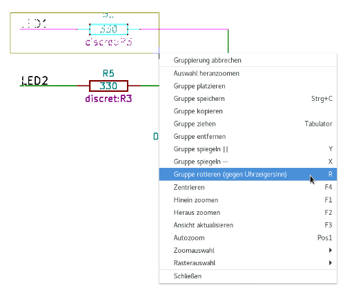
If a block move command has started, another command can be selected using the right-click pop-up menu.
Tastaturbefehle
-
Die "Ctrl+F1" Taste zeigt die aktuelle Liste der Tastaturbefehle an.
-
Hotkeys might be redefined in Controls tab of Schematic Editor Options dialog (menu Preferences → General Options).
Here is the default hotkey list:
Help (this window) |
Ctrl+F1 |
Zoom In |
F1 |
Zoom Out |
F2 |
Zoom Redraw |
F3 |
Zoom Center |
F4 |
Fit on Screen |
Home |
Zoom to Selection |
@ |
Reset Local Coordinates |
Space |
Edit Item |
E |
Delete Item |
Del |
Rotate Item |
R |
Drag Item |
G |
Undo |
Ctrl+Z |
Redo |
Ctrl+Y |
Mouse Left Click |
Return |
Mouse Left Double Click |
End |
Save Schematic |
Ctrl+S |
Load Schematic |
Ctrl+O |
Find Item |
Ctrl+F |
Find Next Item |
F5 |
Find Next DRC Marker |
Shift+F5 |
Find and Replace |
Ctrl+Alt+F |
Repeat Last Item |
Ins |
Move Block → Drag Block |
Tab |
Copy Block |
Ctrl+C |
Paste Block |
Ctrl+V |
Cut Block |
Ctrl+X |
Move Schematic Item |
M |
Duplicate Symbol or Label |
C |
Add Symbol |
A |
Add Power |
P |
Mirror X |
X |
Mirror Y |
Y |
Orient Normal Symbol |
N |
Edit Symbol Value |
V |
Edit Symbol Reference |
U |
Edit Symbol Footprint |
F |
Edit with Symbol Editor |
Ctrl+E |
Begin Wire |
W |
Begin Bus |
B |
End Line Wire Bus |
K |
Add Label |
L |
Add Hierarchical Label |
H |
Add Global Label |
Ctrl+L |
Add Junction |
J |
Add No Connect Flag |
Q |
Add Sheet |
S |
Add Wire Entry |
Z |
Add Bus Entry |
/ |
Add Graphic PolyLine |
I |
Add Graphic Text |
T |
Update PCB from Schematic |
F8 |
Autoplace Fields |
O |
Leave Sheet |
Alt+BkSp |
Delete Node |
BkSp |
Highlight Connection |
Ctrl+X |
All hotkeys can be redefined using the hotkey editor (menu Preferences→General Options→Controls).
It is possible to import/export hotkey settings using menu Preferences→Import and Export→Import/Export Hotkeys.
Grid
In Eeschema the cursor always moves over a grid. The grid can be customized:
-
Size might be changed using the pop-up menu or using the Preferences/Options menu.
-
Color might be changed in Colors tab of the Schematic Editor Options dialog (menu Preferences → General Options).
-
Visibility might be switched using the left-hand toolbar button.
Die Standard Rastergröße ist 50 mil (0.050'') oder 1,27 Millimeter.
This is the preferred grid to place symbols and wires in a schematic, and to place pins when designing a symbol in the Symbol Editor.
One can also work with a smaller grid from 25 mil to 10 mil. This is only intended for designing the symbol body or placing text and comments and not recommended for placing pins and wires.
Zoom Auswahl
Um die Zoom Größe zu verstellen:
-
Betätigen Sie die rechte Maustaste, um das Pop-Up Menü zu öffnen und den gewünschten Zoomlevel auszuwählen.
-
Oder benutzen Sie die Funktionstasten:
-
F1: Zoom in
-
F2: Zoom out
-
F4 or simply click on the middle mouse button (without moving the mouse): Center the view around the cursor pointer position
-
-
Fensterzoom:
-
Mouse wheel: Zoom in/out
-
Shift+Mouse wheel: Pan up/down
-
Ctrl+Mouse wheel: Pan left/right
-
Anzeigen von Cursorkoordinaten
The display units are in inches or millimeters. However, Eeschema always uses 0.001 inch (mil/thou) as its internal unit.
Die folgende Information wird rechts unten im Fenster angezeigt:
-
Der Zoomfaktor
-
Die absolute Position des Cursors
-
Die relative Position des Cursors
The relative coordinates can be reset to zero by pressing Space. This is useful for measuring distance between two points or aligning objects.

Obere Menüleiste
The top menu bar allows the opening and saving of schematics, program configuration and viewing the documentation.

Symbole in der oberen Werkzeugleiste
Diese Werkzeugleiste erlaubt den Zugriff auf die Hauptfunktionen von Eeschema.
Wenn Eeschema im Einzelstehenden Modus ausgeführt wird, zeigt die folgende Grafik die zur Verfügung stehende Werkzeugauswahl:
Note that when KiCad runs in project mode, the first two icons are not available as they work with individual files.
|
Create a new schematic (only in standalone mode). |
|
Open a schematic (only in standalone mode). |
|
Save complete schematic project. |
|
Select the sheet size and edit the title block. |
|
Open print dialog. |
|
Paste a copied/cut item or block to the current sheet. |
|
Undo: Revert the last change. |
|
Redo: Revert the last undo operation. |
|
Show the dialog to search symbols and texts in the schematic. |
|
Show the dialog to search and replace texts in the schematic. |
|
Refresh screen; zoom to fit. |
|
Zoom in and out. |
|
View and navigate the hierarchy tree. |
|
Leave the current sheet and go up in the hierarchy. |
|
Call the symbol library editor to view and modify libraries and symbols. |
|
Browse symbol libraries. |
|
Annotate symbols. |
|
Electrical Rules Checker (ERC), automatically validate electrical connections. |
|
Call CvPcb to assign footprints to symbols. |
|
Export a netlist (Pcbnew, SPICE and other formats). |
|
Edit symbol fields. |
|
Generate the Bill of Materials (BOM). |
|
Call Pcbnew to perform a PCB layout. |
|
Back-import footprint assignment (selected using CvPcb or Pcbnew) into the "footprint" fields. |
Symbole in der rechten Werkzeugleiste
Diese Werkzeugleiste enthält Werkzeuge für:
-
Place symbols, wires, buses, junctions, labels, text, etc.
-
Create hierarchical subsheets and connection symbols.
|
Cancel the active command or tool. |
|
Highlight a net by marking its wires and net labels with a different color. If KiCad runs in project mode then copper corresponding to the selected net will be highlighted in Pcbnew as well. |
|
Display the symbol selector dialog to select a new symbol to be placed. |
|
Display the power symbol selector dialog to select a power symbol to be placed. |
|
Draw a wire. |
|
Draw a bus. |
|
Draw wire-to-bus entry points. These elements are only graphical and do not create a connection, thus they should not be used to connect wires together. |
|
Draw bus-to-bus entry points. |
|
Place a "No Connect" flag. These flags should be placed on symbol pins which are meant to be left unconnected. It is done to notify the Electrical Rules Checker that lack of connection for a particular pin is intentional and should not be reported. |
|
Place a junction. This connects two crossing wires or a wire and a pin, when it can be ambiguous (i.e. if a wire end or a pin is not directly connected to another wire end). |
|
Place a local label. Local label connects items located in the same sheet. For connections between two different sheets, you have to use global or hierarchical labels. |
|
Place a global label. All global labels with the same name are connected, even when located on different sheets. |
|
Place a hierarchical label. Hierarchical labels are used to create a connection between a subsheet and the parent sheet that contains it. |
|
Place a hierarchical subsheet. You must specify the file name for this subsheet. |
|
Import a hierarchical pin from a subsheet. This command can be executed only on hierarchical subsheets. It will create hierarchical pins corresponding to hierarchical labels placed in the target subsheet. |
|
Place a hierarchical pin in a subsheet. This command can be executed only on hierarchical subsheets. It will create arbitrary hierarchical pins, even if they do not exist in the target subsheet. |
|
Draw a line. These are only graphical and do not connect anything. |
|
Place a text comment. |
|
Place a bitmap image. |
|
Delete selected element. |
Symbole der linken Werkzeugleiste
Diese Werkzeugleiste verwaltet die Anzeigeoptionen:
|
Toggle grid visibility. |
|
Switch units to inches. |
|
Switch units to millimeters. |
|
Choose the cursor shape (full screen/small). |
|
Toggle visibility of "invisible" pins. |
|
Toggle free angle/90 degrees wires and buses placement. |
Pop-Up Menüs und Schnellbearbeitung
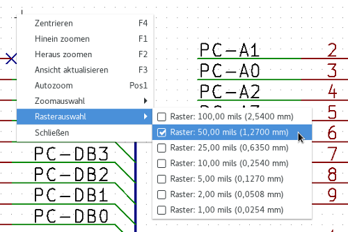
Ein Rechtsklick öffnet ein Kontextmenü für das ausgewählte Element. Dieses enthält:
-
Zoomfaktor.
-
Rasteranpassung.
-
Häufig bearbeitete Parameter des ausgewählten Elements.
Pop-Up Menü ohne ein ausgewähltes Element
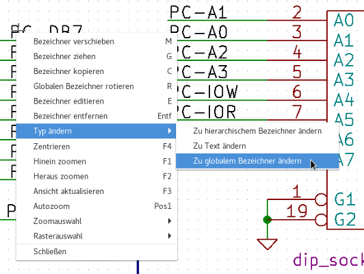
Editing a label.
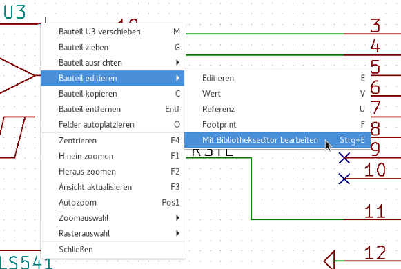
Editing a symbol.
Hauptmenü
Menüpunkt Datei
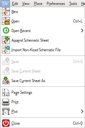
| New | Close current schematic and start a new one (only in standalone mode). |
|---|---|
Open |
Load a schematic project (only in standalone mode). |
Open Recent |
Open a schematic project from the list of recently opened files (only in standalone mode). |
Append Schematic Sheet |
Insert the contents of another sheet into the current one. |
Import Non-Kicad Schematic File |
Imports a schematic project saved in another file format. |
Save |
Save current sheet and all its subsheets. |
Save Current Sheet |
Save only the current sheet, but not others in the project. |
Save Current Sheet As… |
Save the current sheet under a new name. |
Page Settings |
Configure page dimensions and title block. |
Print schematic project (See also chapter Plot and Print). |
|
Plot |
Export to PDF, PostScript, HPGL or SVG format (See chapter Plot and Print). |
Close |
Terminate the application. |
Menüpunkt Einstellungen
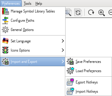
Manage Symbol Library Tables |
Add/remove symbol libraries. |
Configure Paths |
Set the default search paths. |
General Options |
Preferences (units, grid size, field names, etc.). |
Set Language |
Select interface language. |
Icons Options |
Icons visibility settings. |
Import and Export |
Transfer preferences to/from file. |
Manage Symbol Library Tables
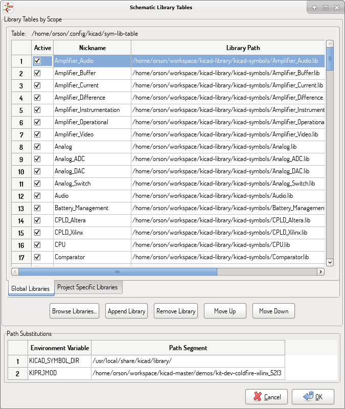
Eeschema uses two library tables to store the list of available symbol libraries, which differ by the scope:
-
Global Libraries
Libraries listed in the Global Libraries table are available to every project. They are saved in sym-lib-table in your home directory (exact path is dependent on the operating system; check the path above the table).
-
Project Specific Libraries
Libraries listed in Project Specific Libraries table are available to the currently opened project. They are saved in sym-lib-table file in the project directory (check the path above the table).
You can view either list by clicking on "Global Libraries" or "Project Specific Libraries" tab below the library table.
Add a new library
Add a library either by clicking Browse Libraries… button and selecting a file or clicking "Append Library" and typing a path to a library file. The selected library will be added to the currently opened library table (Global/Project Specific).
Remove a library
Remove a library by selecting one or more libraries and clicking Remove Library button.
Library properties
Each row in the table stores several fields describing a library:
Active |
Enables/disables the library. It is useful to temporarily reduce the loaded library set. |
Nickname |
Nickname is a short, unique identifier used for assigning symbols to components. Symbols are represented by '<Library Nickname>:<Symbol Name>' strings. |
Library Path |
Path points to the library location. |
Plugin Type |
Determines the library file format. |
Options |
Stores library specific options, if used by plugin. |
Description |
Briefly characterizes the library contents. |
General Options
Display
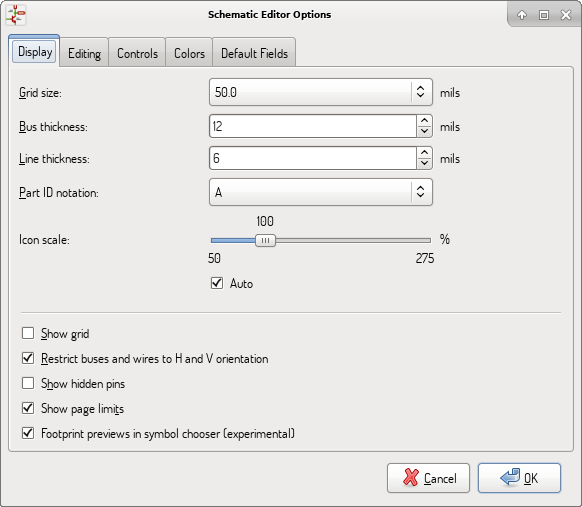
Grid Size |
Grid size selection. It is recommended to work with normal grid (0.050 inches or 1,27 mm). Smaller grids are used for component building. |
Bus thickness |
Pen size used to draw buses. |
Line thickness |
Pen size used to draw objects that do not have a specified pen size. |
Part ID notation |
Style of suffix that is used to denote symbol units (U1A, U1.A, U1-1, etc.) |
Icon scale |
Adjust toolbar icons size. |
Show Grid |
Grid visibility setting. |
Restrict buses and wires to H and V orientation |
If checked, buses and wires are drawn only with vertical or horizontal lines. Otherwise buses and wires can be placed at any orientation. |
Show hidden pins: |
Display invisible (or hidden) pins, typically power pins. |
Show page limits |
If checked, shows the page boundaries on screen. |
Footprint previews in symbol chooser |
Displays a footprint preview frame and footprint selector when placing a new symbol. Note: it may cause problems or delays, use at your own risk. |
Editing
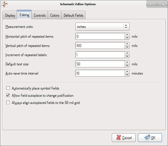
Measurement units |
Select the display and the cursor coordinate units (inches or millimeters). |
Horizontal pitch of repeated items |
Increment on X axis during element duplication (default: 0) (after placing an item like a symbol, label or wire, a duplication is made by the Insert key) |
Vertical pitch of repeated items |
Increment on Y axis during element duplication (default: 0.100 inches or 2,54 mm). |
Increment of repeated labels |
Increment of label value during duplication of texts ending in a number, such as bus members (usual value 1 or -1). |
Default text size |
Text size used when creating new text items or labels. |
Auto-save time interval |
Time in minutes between saving backups. |
Automatically place symbol fields |
If checked, symbol fields (e.g. value and reference) in newly placed symbols might be moved to avoid collisions with other items. |
Allow field autoplace to change justification |
Extension of 'Automatically place symbol fields' option. Enable text justification adjustment for symbol fields when placing a new part. |
Always align autoplaced fields to the 50 mil grid |
Extension of 'Automatically place symbol fields' option. If checked, fields are autoplaced using 50 mils grid, otherwise they are placed freely. |
Controls
Redefine hotkeys and set up the user interface behavior.
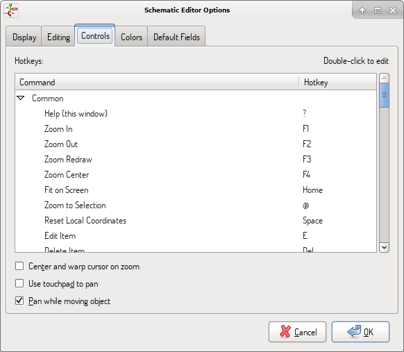
Select a new hotkey by double clicking an action or right click on an action to show a popup menu:
Edit |
Define a new hotkey for the action (same as double click). |
Undo Changes |
Reverts the recent hotkey changes for the action. |
Restore Default |
Sets the action hotkey to its default value. |
Undo All Changes |
Reverts all recent hotkey changes for the action. |
Restore All to Default |
Sets all action hotkeys to their default values. |
Options description:
Center and warp cursor on zoom |
If checked, the pointed location is warped to the screen center when zooming in/out. |
Use touchpad to pan |
When enabled, view is panned using scroll wheels (or touchpad gestures) and to zoom one needs to hold Ctrl. Otherwise scroll wheels zoom in/out and Ctrl/Shift are the panning modifiers. |
Pan while moving object |
If checked, automatically pans the window if the cursor leaves the window during drawing or moving. |
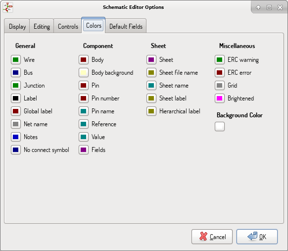
Colors
Color scheme for various graphic elements. Click on any of the color swatches to select a new color for a particular element.
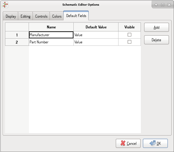
Default Fields
Define additional custom fields and corresponding values that will appear in newly placed symbols.
Menüpunkt Hilfe
Access to on-line help (this document) for an extensive tutorial about KiCad.
Use ``Copy Version Information'' when submitting bug reports to identify your build and system.
Obere Werkzeugleiste
Einrichten des Zeichenblattes
The Sheet Settings icon (![]() ) allows you to define the sheet size and the contents of the title block.
) allows you to define the sheet size and the contents of the title block.
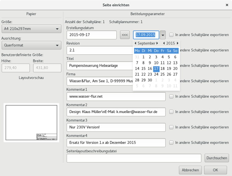
Die Blattnummerierung wird automatisch aktualisiert. Sie können das heutige Datum setzen, indem Sie auf den Button mit den linksgerichteten Pfeilen bei "Datum festlegen" drücken, es wird aber später nicht automatisch geändert.
Suchwerkzeug
The Find icon (![]() ) can be used to access the search tool.
) can be used to access the search tool.
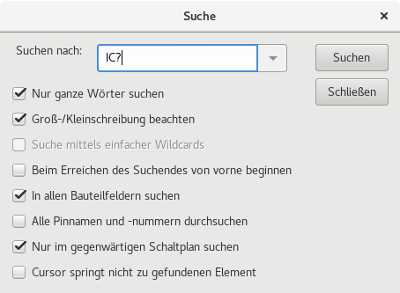
You can search for a reference, a value or a text string in the current sheet or in the whole hierarchy. Once found, the cursor will be positioned on the found element in the relevant sub-sheet.
Netzlisten Werkzeug
The Netlist icon (![]() ) opens the netlist generation tool.
) opens the netlist generation tool.
The tool creates a file which describe all connections in the entire hierarchy.
In a multisheet hierarchy, any local label is visible only inside the sheet to which it belongs. For example: the label LABEL1 of sheet 3 is different from the label LABEL1 of sheet 5 (if no connection has been intentionally introduced to connect them). This is due to the fact that the sheet name path is internally associated with the local label.
| Even though there is no text length limit for labels in Eeschema, please take into account that other programs reading the generated netlist may have such constraints. |
| Avoid spaces in labels, because they will appear as separated words in the generated file. It is not a limitation of Eeschema, but of many netlist formats, which often assume that a label has no spaces. |
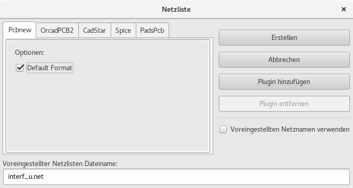
Optionen:
Default Format |
Check to select Pcbnew as the default format. |
Andere Formate können ebenfalls erzeugt werden:
-
Orcad PCB2
-
CadStar
-
Spice (simulators)
External plugins can be added to extend the netlist formats list (PadsPcb Plugin was added in the picture above).
There is more information about creating netlists in Create a Netlist chapter.
Das Annotation (Beschriftungs) Werkzeug
The icon ![]() launches the annotation tool. This tool assigns references to components.
launches the annotation tool. This tool assigns references to components.
Für mehrteilige Bauteile (z.B. ein 4-fach-NAND Gatter der 7400 TTL Familie), wird ein Mehrteil-Suffix erzeugt (daher wird ein 7400 TTL mit dem Bezeichner U3 aufgeteilt in U3A, U3B, U3C und U3D).
You can unconditionally annotate all the components or only the new components, i.e. those which were not previously annotated.
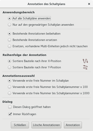
Anwendungsbereich
| Use the entire schematic | All sheets are re-annotated (default). |
|---|---|
Use the current page only |
Only the current sheet is re-annotated (this option is to be used only in special cases, for example to evaluate the amount of resistors in the current sheet.). |
Keep existing annotation |
Conditional annotation, only the new components will be re-annotated (default). |
Reset existing annotation |
Unconditional annotation, all the components will be re-annotated (this option is to be used when there are duplicated references). |
Reset, but do not swap any annotated multi-unit parts |
Keeps all groups of multiple units (e.g. U2A, U2B) together when reannotating. |
Reihenfolge der Annotation
Selects the order in which components will be numbered (either horizontally or vertically).
Annotationsauswahl
Selects the assigned reference format.
ERC Werkzeug
The icon ![]() launches the electrical rules check (ERC) tool.
launches the electrical rules check (ERC) tool.
This tool performs a design verification and is able to detect forgotten connections, and inconsistencies.
Once you have run the ERC, Eeschema places markers to highlight problems. The error description is displayed after left clicking on the marker. An error report file can also be generated.
ERC Bericht
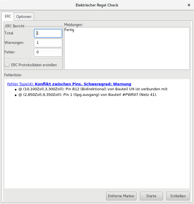
Errors are displayed in the Electrical Rules Checker dialog:
-
Total: Komplette Zahl der Fehler und Warnungen.
-
Fehler: Anzahl der aufgetretenen Fehler
-
Warnungen: Anzahl der Warnungen
Optionen:
Create ERC file report |
Check this option to generate an ERC report file. |
Befehle:
Delete Markers |
Remove all ERC error/warnings markers. |
Run |
Start an Electrical Rules Check. |
Close |
Close the dialog. |
-
Klicken auf eine Fehlermeldung springt zur zugehörigen Markierung im Schaltplan.
ERC Optionen Dialog
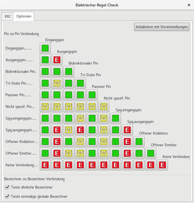
This tab allows you to define the connectivity rules between pins; you can choose between 3 options for each case:
-
Kein Fehler
-
Warnung
-
Fehler
Jedes Kästchen der Matrix kann durch anklicken verändert werden.
Optionen:
Test similar labels |
Report labels that differ only by letter case (e.g. label/Label/LaBeL). Net names are case-sensitive therefore such labels are treated as separate nets. |
Test unique global labels |
Report global lables that occur only once for a particular net. Normally it is required to have at least two make a connection. |
Befehle:
Initialize to Default |
Restores the original settings. |
Stücklistenwerkzeug
The icon ![]() launches the bill of materials (BOM) generator. This tool generates a file listing the components and/or hierarchical connections (global labels).
launches the bill of materials (BOM) generator. This tool generates a file listing the components and/or hierarchical connections (global labels).
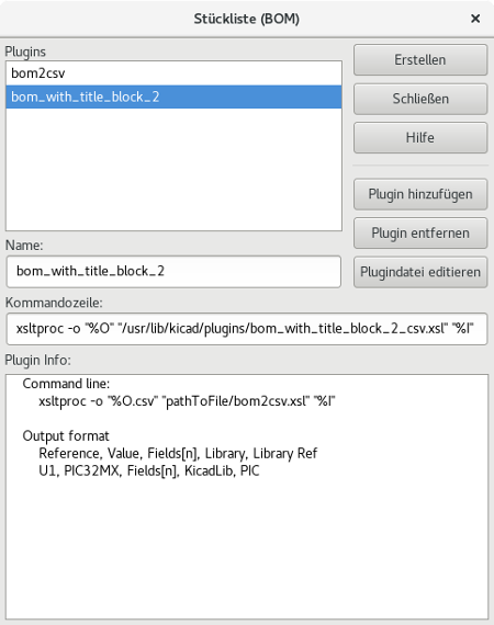
Eeschema’s BOM generator makes use of external plugins, either as XSLT or Python scripts. There are a few examples installed inside the KiCad program files directory.
Ein hilfreicher Satz von Bauteileigenschaften die in einer Stückliste (BOM) verwendet werden können:
-
Wert: eindeutiger Name für jedes verwendete Bauteil
-
Footprint - entweder manuell gesetzt oder "zurück-annotiert" (siehe unten).
-
Feld1 - Name des Herstellers
-
Feld2 - Teilenummer des Herstellers
-
Feld3 - Teilenummer des Distributors
Zum Beispiel:
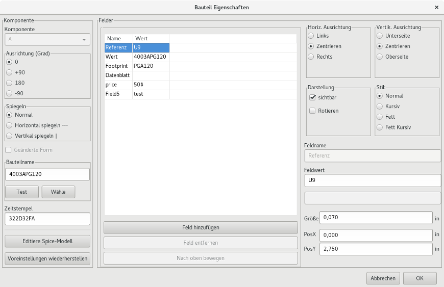
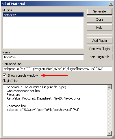
On MS Windows, BOM generator dialog has a special option (pointed by red arrow) that controls visibility of external plugin window. + By default, BOM generator command is executed console window hidden and output is redirected to Plugin info field. Set this option to show the window of the running command. It may be necessary if plugin has provides a graphical user interface.
Edit Fields tool
The icon ![]() opens a spreadsheet to view and modify field values for all symbols.
opens a spreadsheet to view and modify field values for all symbols.
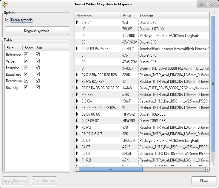
Once you modify field values, you need to either accept changes by clicking on 'Apply' button or undo them by clicking on 'Revert' button.
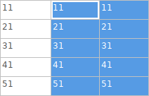
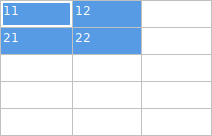
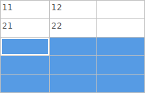
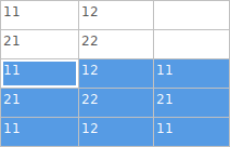
Tricks to simplify fields filling
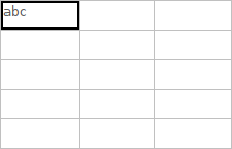
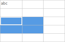
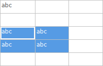
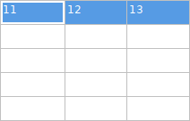
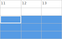
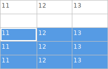
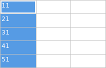
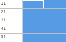
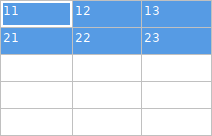
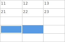
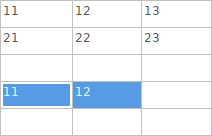
There are several special copy/paste methods in spreadsheet. They may be useful when entering field values that are repeated in a few components.
These methods are illustrated below.
| Copy (Ctrl+C) | Selection | Paste (Ctrl+V) |
|---|---|---|
|
|
|
|
|
|
|
|
|
|
|
|
|
|
|
| These techniques are also available in other dialogs with a grid control element. |
Import tool for footprint assignment
Zugriff:
The icon ![]() launches the back-annotate tool.
launches the back-annotate tool.
Dieses Werkzeug erlaubt es, Footprintänderungen die in Pcbnew gemacht wurden, zurück in die Footprintfelder in Eeschema zu importieren.
Manage Symbol Libraries
Symbol libraries hold collections of symbols used when creating schematics. Each symbol in a schematic is uniquely identified by a full name that is composed of a library nickname and a symbol name. An example is Audio:AD1853.
Symbol Library Table
The symbol library table holds a list of all library files KiCad knows about. The symbol library table is constructed from the global symbol library table file and the project specific symbol library table file.
When a symbol is loaded, Eeschema uses the library nickname, Audio in our example, to lookup the library location in the symbol library table.
The image below shows the symbol library table editing dialog which can be opened by invoking the Manage Symbol Library Tables'' entry in the Preferences'' menu.

Global Symbol Library Table
The global symbol library table contains the list of libraries that are always available regardless of the currently loaded project file. The table is saved in the file sym-lib-table in the user’s home folder. The location of this folder is dependent upon the operating system being used.
Project Specific Symbol Library Table
The project specific symbol library table contains the list of libraries that are available specifically for the currently loaded project file. The project specific symbol library table can only be edited when it is loaded along with the project file. If no project file is loaded or there is no symbol library table file in the current project path, an empty table is created which can be edited and later saved along with the project file.
Initial Configuration
The first time Eeschema is run and the global symbol table file sym-lib-table is not found in the user’s home folder, Eeschema will attempt to copy the default symbol table file sym-lib-table stored in the system’s KiCad template folder to the file sym-lib-table in the user’s home folder. If the default template sym-lib-table file cannot be found, a dialog will prompt for an alternate location for the sym-lib-table file. If no sym-lib-table is found or the dialog is dismissed, an empty symbol library table will be created in the user’s home folder. If this happens, the user can either copy sym-lib-table manually or configure the table by hand.
|
The default symbol library table includes all of the symbol libraries that are installed as part of KiCad. This may or may not be desirable depending on usages and the speed of the system. The amount of time required to load the symbol libraries is proportional to the number of libraries in the symbol library table. If symbol library load times are excessive, remove rarely and/or never used libraries from the global library table and add them to the project library table as required. |
Adding Table Entries
In order to use a symbol library, it must first be added to either the global table or the project specific table. The project specific table is only applicable when you have a project file open.
Each library entry must have a unique nickname.
This does not have to be related in any way to the actual library file name or path. The colon ':' and '/' characters cannot be used anywhere in the library nickname. Each library entry must have a valid path and/or file name depending on the type of library. Paths can be defined as absolute, relative, or by environment variable substitution (see section below).
The appropriate plug in type must be selected in order for the library to be properly read. KiCad currently supports only legacy symbol library files plug-in.
There is also a description field to add a description of the library entry. The option field is not used at this time so adding options will have no effect when loading libraries.
-
Please note that you cannot have duplicate library nicknames in the same table. However, you can have duplicate library nicknames in both the global and project specific symbol library table.
-
The project specific table entry will take precedence over the global table entry when duplicate nicknames occur.
-
When entries are defined in the project specific table, a sym-lib-table file containing the entries will be written into the folder of the currently open project file.
Environment Variable Substitution
One of the most powerful features of the symbol library table is environment variable substitution. This allows for definition of custom paths to where symbol libraries are stored in environment variables. Environment variable substitution is supported by using the syntax $\{ENV_VAR_NAME\} in the library path.
By default, at run time KiCad defines two environment variables:
-
the KIPRJMOD environment variable that always points to the currently open project directory. KIPRJMOD cannot be modified.
-
the KICAD_SYMBOL_DIR environment variable. This points to the path where the default symbol libraries that were installed with KiCad.
You can override KICAD_SYMBOL_DIR by defining it yourself in preferences/ Configure Path which allows you to substitute your own libraries in place of the default KiCad symbol libraries.
KIPRJMOD allows you to store libraries in the project path without having to define the absolute path (which is not always known) to the library in the project specific symbol library table.
Usage Patterns
Symbol libraries can be defined either globally or specifically to the currently loaded project. Symbol libraries defined in the user’s global table are always available and are stored in the sym-lib-table file in the user’s home folder. The project specific symbol library table is active only for the currently open project file.
There are advantages and disadvantages to each method. Defining all libraries in the global table means they will always be available when needed. The disadvantage of this is that load time will increase.
Defining all symbol libraries on a project specific basis means that you only have the libraries required for the project which decreases symbol library load times. The disadvantage is that you always have to remember to add each symbol library that you need for every project.
One usage pattern would be to define commonly used libraries globally and the libraries only required for the project in the project specific library table. There is no restriction on how to define libraries.
Legacy Project Remapping
When loading a schematic created prior to the symbol library table implementation, Eeschema will attempt to remap the symbol library links in the schematic to the appropriate library table symbols. The success of this process is dependent on several factors:
-
the original libraries used in the schematic are still available and unchanged from when the symbol was added to the schematic.
-
all rescue operations were performed when detected to create a rescue library or keep the existing rescue library up to date.
-
the integrity of the project symbol cache library has not been corrupted.
|
The remapping will make a back up of all the files that are changed during remapping in the rescue-backup folder in the project folder. Always make a back up of your project before remapping just in case something goes wrong. |
|
The rescue operation is performed even if it has been disabled to ensure the correct symbols are available for remapping. Do not cancel this operation or the remapping will fail to correctly remap schematics symbols. Any broken symbol links will have to be fixed manually. |
|
If the original libraries have been removed and the rescue was not performed, the cache library can be used as a recovery library as a last resort. Copy the cache library to a new file name and add the new library file to the top of the library list using a version of Eeschema prior to the symbol library table implementation. |
Erstellung und Bearbeitung eines Schaltplans
Einleitung
Ein Schaltplan kann auf einem einzelnen Blatt dargestellt werden, aber wenn er groß genug ist wird er mehrere Blätter benötigen.
Ein Schaltplan der auf mehreren Seiten erstellt wird, ist hierarchisch und alle seine Blätter (jedes Blatt ist eine eigene Datei) stellen ein Eeschema-Projekt dar. Die Bearbeitung von hierarchischen Schaltplänen wird im Kapitel Hierarchische Schaltpläne beschrieben.
Allgemeine Betrachtungen
Ein Schaltplan der mit Eeschema erstellt wird, ist mehr als eine einfache grafische Darstellung eines elektronischen Schaltkreises. Er ist normalerweise der Startpunkt einer Entwicklungskette, die es erlaubt:
-
Prüfungen unter zu Hilfenahme von Regelsätzen (Elektrischer-Regel-Prüfung (ERC)) können durchgeführt werden um Fehler und Auslassungen zu erkennen.
-
Automatisches Erstellen eine Stückliste (BOM).
-
Benutzung einer Software zur Simulation wie zum Beispiel SPICE, siehe Netzliste erzeugen.
-
Eine Netzliste erzeugen für die Übertragung zum Leiterplatten-Layout.
A schematic mainly consists of symbols, wires, labels, junctions, buses and power ports. For clarity in the schematic, you can place purely graphical elements like bus entries, comments, and polylines.
Die Entwicklungskette
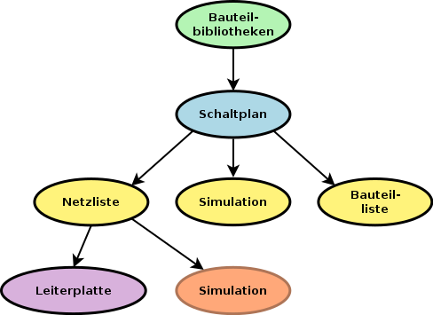
Symbols are added to the schematic from symbol libraries. After the schematic is made, a netlist is generated, which is later used to import the set of connections and footprints into PcbNew.
Symbol placement and editing
Find and place a symbol
To load a symbol into your schematic you can use the icon ![]() . A dialog box allows you to type the name of the symbol to load.
. A dialog box allows you to type the name of the symbol to load.
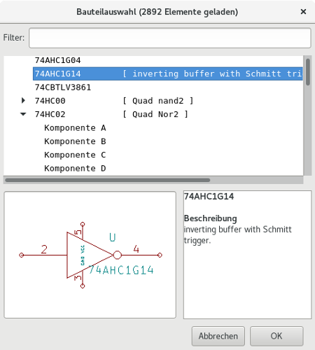
The Choose Symbols dialog will filter symbols by name, keywords, and description according to what you type into the search field. Advanced filters can be used just by typing them:
-
Wildcards: use the characters
?and*respectively to mean "any character" and "any number of characters". -
Relational: if a library part’s description or keywords contain a tag of the format "Key:123", you can match relative to that by typing "Key>123" (greater than), "Key<123" (less than), etc. Numbers may include one of the following case-insensitive suffixes:
p
n
u
m
k
meg
g
t
10-12
10-9
10-6
10-3
103
106
109
1012
ki
mi
gi
ti
210
220
230
240
-
Regular expression: if you’re familiar with regular expressions, these can be used too. The regular expression flavor used is the wxWidgets Advanced Regular Expression style, which is similar to Perl regular expressions.
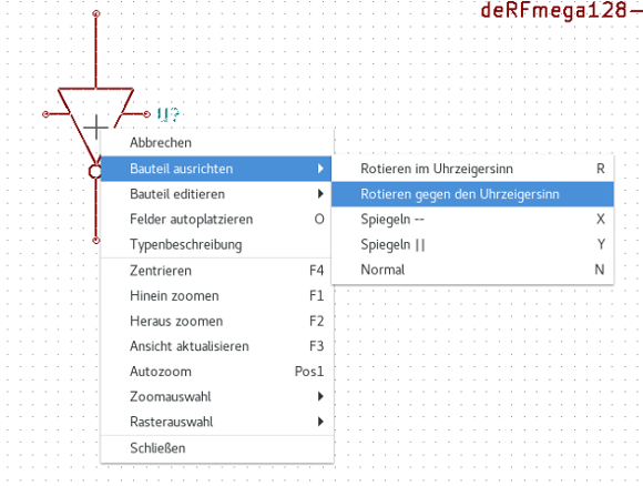
Before placing the symbol in the schematic, you can rotate it, mirror it, and edit its fields, by either using the hotkeys or the right-click context menu. This can be done the same way after placement.
Here is a symbol during placement:
Spannungsversorgungen
A power port symbol is a symbol (the symbols are grouped in the “power” library), so they can be placed using the symbol chooser. However, as power placements are frequent, the ![]() tool is available. This tool is similar, except that the search is done directly in the ``power'' library.
tool is available. This tool is similar, except that the search is done directly in the ``power'' library.
Symbol Editing and Modification (already placed component)
There are two ways to edit a symbol:
-
Modification of the symbol itself: position, orientation, unit selection on a multi-unit symbol.
-
Modification of one of the fields of the symbol: reference, value, footprint, etc.
When a symbol has just been placed, you may have to modify its value (particularly for resistors, capacitors, etc.), but it is useless to assign to it a reference number right away, or to select the unit (except for components with locked units, which you have to assign manually). This can be done automatically by the annotation function.
Symbol modification
To modify some feature of a symbol, position the cursor on the symbol, and then either:
-
Double-click on the symbol to open the full editing dialog.
-
Mit einem Rechtsklick das Kontextmenü zu öffnen und einen der Befehle Bewegen, Ausrichtung, Bearbeiten, Löschen, usw. auswählen.
Textfelder eines Bauteils ändern
Sie können die Referenz, den Wert, die Position, die Ausrichtung, die Textgröße und Sichtbarkeit der Felder durch folgende Möglichkeiten ändern:
-
Doppelklick auf das Textfeld, um es zu ändern.
-
Rechtsklick um das Kontextmenü zu öffnen und einen der Befehle benutzen: Bewegen, Drehen, Bearbeiten, Löschen, usw.
For more options, or in order to create fields, double-click on the symbol to open the Symbol Properties dialog.

Each field can be visible or hidden, and displayed horizontally or vertically. The displayed position is always indicated for a normally displayed symbol (no rotation or mirroring) and is relative to the anchor point of the symbol.
The option “Reset to Library Defaults” sets the symbol to the original orientation, and resets the options, size and position of each field. However, texts fields are not modified because this could break the schematic.
Leitungen, Busse, Label, Spannungsversorgungen
Einleitung
All diese Zeichnungselemente können ebenfalls mit den Werkzeugen der vertikalen rechten Werkzeugleiste platziert werden.
Diese Elemente sind:
-
Wires: most connections between symbols.
-
Busse: um Bus Labels grafisch zu verbinden
-
Polylinien: für grafische Darstellung.
-
Verbindungen: um Verbindungen zwischen gekreuzten Leitungen oder Bussen herzustellen.
-
Bus entries: to show connections between wires and buses.
-
Label: um Leitungen zu benennen oder Verbindungen herzustellen.
-
Globale Label: für Verbindungen zwischen Blättern.
-
Texte: für Kommentare und Anmerkungen.
-
"Keine Verbindung" Kennzeichnung: um einen Anschluss abzuschließen, der keine Verbindung braucht.
-
Hierarchische Blätter, und ihre Verbindungsanschlüsse.
Verbindungen (Leitungen und Label)
Es gibt zwei Möglichkeiten eine Verbindung zu erstellen:
-
Pin zu Pin Verbindungen
-
Label
Das folgende Bild zeigt die beiden Methoden:
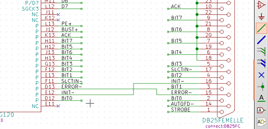
Anmerkung 1:
Der "Anschluss"-Punkt eines Labels ist die untere linke Ecke des ersten Buchstaben des Labels. Dieser Punkt wird mit einem kleinen Quadrat dargestellt, wenn er nicht verbunden ist.
Dieser Punkt muss daher Kontakt zur Leitung haben oder am Ende eines Anschlusses überlagert werden, sodass das Label als verbunden angesehen wird.
Anmerkung 2:
Um eine Verbindung herzustellen, muss ein Teil der Leitung mit seinen Enden an ein anderes Segment oder einen Pin angeschlossen sein.
Wenn es eine Überlappung gibt (wenn eine Leitung über einen Anschluss läuft aber nicht zum Anschluss verbunden wird), gibt es keine Verbindung.
Anmerkung 3:
Leitungen die sich kreuzen sind nicht implizit verbunden. Es ist notwendig, sie mit einem Verbindungspunkt zu verbinden, wenn eine Verbindung gewünscht ist.
Das vorstehende Bild (Leitungen verbunden mit DB25FEMALE Pins 22, 21, 20, 19 ) zeigt so einen Fall einer Verbindung mit einem Verbindungspunkt.
Anmerkung 4:
Wenn zwei unterschiedliche Labels an der gleichen Leitung platziert werden, werden sie verbunden und werden äquivalent: alle anderen Elemente die mit einem der beiden Label verbunden sind, sind mit allen anderen verbunden.
Verbindungen (Busse)
Im folgenden Schaltplan sind viele Anschlüsse zu Bussen verbunden.
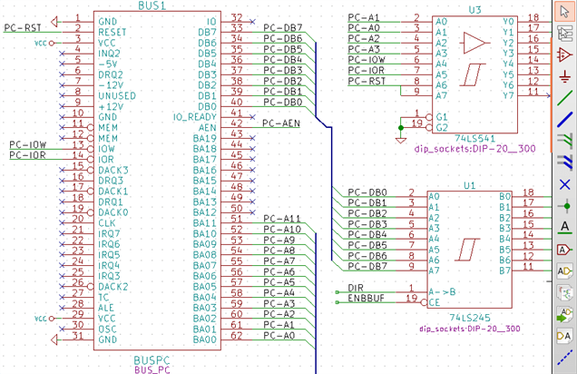
Mitglieder eines Buses
Aus Sicht des Schaltplans ist ein Bus eine Ansammlung von Signalen, die mit einem gemeinsamen Prefix starten und auf eine Nummer enden. Zum Beispiel PCA0, PCA1 und PCA2 sind Mitglieder des PCA Bus.
Der komplette Bus ist benannt PCA[N..m], wobei N und m die ersten und letzten Leitungs-Nummern dieses Busses sind. Wenn PCA also 20 Mitglieder von 0 bis 19 hat, wird der gesamte Bus mit PCA[0..19] bezeichnet. Eine Sammlung wie PCA0, PCA1, WRITE, READ kann nicht in einem Bus zusammengefasst werden.
Verbindungen zwischen Bus-Mitgliedern
Anschlüsse zwischen den gleichen Mitgliedern eines Busses müssen über Labels verbunden werden. Es ist nicht möglich einen Anschluss direkt an einen Bus zu verbinden; diese Art der Verbindung wird von Eeschema ignoriert.
Im Beispiel oben sind Verbindungen über Labels hergestellt, die an Leitungen platziert wurden, die an Pins angeschlossen sind. Buseingänge (Leitungssegmente mit 45 Grad) zu Bussen sind rein grafisch und nicht notwendig um logische Verbindungen herzustellen.
Wenn die Bauteilanschlüsse in aufsteigender Reihenfolge angeordnet sind können über den Wiederholungsbefehl (Einfg Taste) Verbindungen sehr schnell in folgender Weise hergestellt werden. Dies ist ein üblicher Fall in der Praxis bei Bauteilen wie Speichern, Mikroprozessoren.
-
Platzieren Sie das erste Label (zum Beispiel PCA0)
-
Nutzen Sie den Wiederholungsbefehl so oft wie nötig um die Mitglieder zu platzieren. Eeschema wird automatisch die nächsten Labels (PCA1, PCA2, …) senkrecht angeordnet an der theoretischen Position der anderen Anschlüsse erzeugen.
-
Zeichnen Sie die Leitung unter dem ersten Label. Dann nutzen Sie den Wiederholungsbefehl um die anderen Leitungen unter den Labels zu platzieren.
-
Wenn nötig platzieren sie die Buseingänge in der gleichen Weise (ersten Eingang platzieren, dann den Wiederholungsbefehl nutzen).
|
Im Menü "Einstellungen → Einstellungen des Schaltplaneditors" können Sie die Parameter für die Wiederholungen einstellen:
|
Globale Verbindung zwischen Bussen
Es kann sein, dass Sie Verbindungen zwischen Bussen brauchen, um zwei Busse mit unterschiedlichen Namen, oder im Falle einer Hierarchie, um zwei unterschiedliche Blätter zu verbinden. Diese Verbindungen können Sie in folgender Weise erstellen.
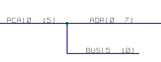
Die Busse PCA[0..15], ADR[0..7] und BUS[5..10] sind miteinander verbunden. Beachten Sie den Verbindungspunkt hier, der die vertikale Busleitung mit der dem mittlerem und horizontalen Bussegment verbindet.
Um genau zu sein, folgende Mitglieder sind miteinander verbunden: PCA0, ADR0 sind verbunden (das Gleiche wie PCA1 und ADR1 … PCA1 und ADR7).
Weiterhin sind PCA5, BUS5 und ADR5 verbunden (genauso wie PCA6, BUS6 und ADR6 und analog wie PCA7, BUS7 und ADR7).
PCA8 und BUS8 sind ebenfalls verbunden (genau wie PCA9 und BUS9, PCA10 und BUS10).
Verbindungen von Spannungsversorgungen
When the power pins of the symbols are visible, they must be connected, as for any other signal.
Symbols such as gates and flip-flops may have invisible power pins. Care must be taken with these because:
-
Sie können keine Leitungen anschließen, weil sie nicht sichtbar sind.
-
Sie kennen die Namen der Anschlüsse nicht.
Zusätzlich wäre es eine schlechte Idee diese sichtbar zu machen und diese wie andere Pins anzuschließen, der Schaltplan würde schlechter lesbar und nicht mit den üblichen Konventionen überein stimmen.
|
Wenn Sie die Anzeige der nicht sichtbaren Anschlüsse erzwingen wollen, müssen Sie die Option "Versteckte Pins einblenden" im Menü "Einstellungen" → "Einstellungen des Schaltplaneditors" Tab "Darstellung" einschalten oder über das Symbol |
Eeschema verbindet automatisch ausgeblendete Spannungsanschlüsse mit gleichem Namen zu einem Spannungsnetz mit diesem Namen. Es mag nötig sein Spannungsnetze mit unterschiedlichen Namen zu verbinden (zum Beispiel "GND" in TTL Bauteilen und "VSS" in MOS Bauteilen); benutzen Sie Spannungsversorgungen dafür.
Es wird nicht empfohlen Label für die Verbindung von Spannungsnetzen zu benutzen. Diese haben nur einen lokalen Verbindungsfokus und würden ausgeblendete Spannungsanschlüsse nicht verbinden.
Das Bild unten zeigt ein Beispiel für Leistungsanschluss-Verbindungen.
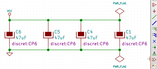
In diesem Beispiel ist Masse (GND) mit dem Spannungsanschluss VSS verbunden, und Spannungsanschluss VCC ist verbunden mit VDD.
Zwei PWR_FLAG Symbole sind hier zu sehen. Sie zeigen an, dass die zwei Spannungsanschlüsse VCC und GND tatsächlich mit einer Spannungsquelle verbunden sind. Ohne diese beiden Symbole würde das ERC-Werkzeug folgendes erkennen: Warning: power port not powered.
All these symbols can be found in the ``power'' symbol library.
``No Connect'' flag
These symbols are very useful to avoid undesired ERC warnings. The electrical rules check ensures that no connection has been accidentally left unconnected.
Wenn Anschlüsse wirklich unverbunden bleiben sollen ist es notwendig ein "Keine Verbindung" Markierung an diesen Anschlüssen zu platzieren (Werkzeug ![]() ). Diese Symbole haben keinen Einfluss auf die erzeugte Netzliste.
). Diese Symbole haben keinen Einfluss auf die erzeugte Netzliste.
Zeichnungsergänzungen
Textkommentare
It can be useful (to aid in understanding the schematic) to place annotations such as text fields and frames. Text fields (tool ![]() ) and Polyline (tool
) and Polyline (tool ![]() ) are intended for this use, contrary to labels and wires, which are connection elements.
) are intended for this use, contrary to labels and wires, which are connection elements.
Hier finden sie ein Beispiel für einen Rahmen mit einem Textkommentar.
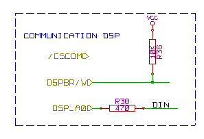
Seite einrichten -Titelblock
Der Titelblock wird über das Werkzeug ![]() bearbeitet.
bearbeitet.


Die Schaltplannummer (Sheet: X/Y) wird automatisch aktualisiert.
Rescuing cached symbols
By default, Eeschema loads symbols from the project libraries according to the set paths and library order. This can cause a problem when loading a very old project: if the symbols in the library have changed or have been removed or the library no longer exists since they were used in the project, the ones in the project would be automatically replaced with the new versions. The new versions might not line up correctly or might be oriented differently leading to a broken schematic.
When a project is saved, a cache library with the contents of the current library symbols is saved along with the schematic. This allows the project to be distributed without the full libraries. If you load a project where symbols are present both in its cache and in the system libraries, Eeschema will scan the libraries for conflicts. Any conflicts found will be listed in the following dialog:
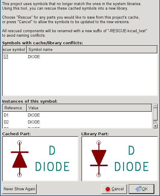
You can see in this example that the project originally used a diode with the cathode facing up, but the library now contains one with the cathode facing down. This change would break the schematic! Pressing OK here will cause the symbol cache library to be saved into a special ``rescue'' library and all the symbols are renamed to avoid naming conflicts.
If you press Cancel, no rescues will be made, so Eeschema will load all the new components by default. If you save the schematic at this point, your cache will be overwritten and the old symbols will not be recoverable. If you have saved the schematic, you can still go back and run the rescue function again by selecting "Rescue Cached Components" in the "Tools" menu to call up the rescue dialog again.
If you would prefer not to see this dialog, you can press "Never Show Again". The default will be to do nothing and allow the new components to be loaded. This option can be changed back in the Libraries preferences.
Hierarchische Schaltpläne
Einleitung
Eine hierarchische Darstellung ist im Allgemeinen eine gute Lösung für Projekte die größer als ein paar Arbeitsblätter sind. Wenn Sie solch eine Art von Projekt verwalten müssen dann ist es nötig:
-
Große Arbeitsblätter zu verwenden, was in Problemen beim Ausdrucken und Handhaben endet.
-
Mehrere Blätter zu verwenden, was Sie zu einer hierarchischen Struktur hinführt.
Der komplette Schaltplan besteht dann aus einem Hauptschaltplan, auch Hauptblatt genannt, und Unterblättern, die die Hierarchie darstellen. Zudem erhöht ein geschicktes Unterteilen des Entwurfs in separate Blätter oft die Lesbarkeit.
Vom Hauptblatt aus müssen Sie in der Lage sein alle Unterblätter zu erreichen. Hierarchische Schaltplanverwaltung ist in Eeschema dank des integrierten "Hierarchie-Navigators" sehr einfach, erreichbar über das Symbol ![]() in der oberen Werkzeugleiste.
in der oberen Werkzeugleiste.
There are two types of hierarchy that can exist simultaneously: the first one has just been evoked and is of general use. The second consists in creating symbols in the library that appear like traditional symbols in the schematic, but which actually correspond to a schematic which describes their internal structure.
Diese zweite Art wird verwendet um integrierte Schaltungen zu entwickeln, weil Sie in diesem Fall Funktionsbibliotheken in dem zu zeichnenden Schaltplan nutzen müssen.
Eeschema unterstützt derzeit diese zweite Möglichkeit nicht!
Eine Hierarchie kann folgende Art haben:
-
Einfach: Ein gegebenes Blatt wird nur einmal verwendet.
-
Komplex: Ein gegebenes Blatt wird mehr als einmal verwendet (mehrfache Instanzen).
-
Flach: Das ist eine einfache Hierarchie, aber es werden keine Verbindungen zwischen Blättern gezeichnet.
Eeschema kann mit all diesen Hierarchien umgehen.
Das Erstellen eines hierarchischen Schaltplans ist einfach, die komplette Hierarchie wird vom Hauptschaltplan aus gehandhabt, als hätten Sie nur einen Schaltplan.
Die zwei wichtigen zu verstehenden Punkte sind:
-
Wie erstellt man ein Unterblatt?
-
How to build electrical connections between sub-sheets.
Bewegen in der Hierarchie
Navigation among sub-sheets is acheived by using the navigator tool accessible via the button ![]() on the top toolbar.
on the top toolbar.
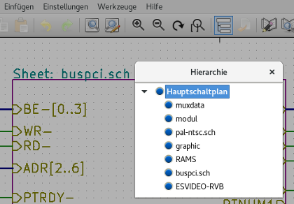
Each sheet is reachable by clicking on its name. For quick access, right click on a sheet name, and choose to Enter Sheet or double click within the bounds of the sheet.
In order to exit the current sheet to the parent sheet, right click anywhere in the schematic where there is no object and select "Leave Sheet" in the context menu or press Alt+Backspace.
Lokale, hierarchische und globale Label
Eigenschaften
Lokale Label (Werkzeug ![]() ) verbinden Signale nur innerhalb eines Blattes. Hierarchische Label (Werkzeug
) verbinden Signale nur innerhalb eines Blattes. Hierarchische Label (Werkzeug ![]() ) verbinden Signale nur innerhalb eines Blattes und zu einem hierarchischen Anschluss im übergeordneten Blatt.
) verbinden Signale nur innerhalb eines Blattes und zu einem hierarchischen Anschluss im übergeordneten Blatt.
Globale Label (Werkzeug ![]() ) verbinden Signale über alle Hierarchieebenen. Unsichtbare Spannungsversorgungsanschlüsse (Typ Spannungseingang und Spannungsausgang) sind wie globale Label, da diese über die gesamte Hierarchie als verbunden behandelt werden.
) verbinden Signale über alle Hierarchieebenen. Unsichtbare Spannungsversorgungsanschlüsse (Typ Spannungseingang und Spannungsausgang) sind wie globale Label, da diese über die gesamte Hierarchie als verbunden behandelt werden.
| Innerhalb einer Hierarchie (einfach oder komplex) können Sie sowohl hierarchische als auch globale Label verwenden. |
Summary of hierarchy creation
Folgendes müssen Sie tun:
-
Platzieren sie im Hauptblatt ein Hierarchiesymbol "Blattsymbol".
-
Öffnen Sie den neuen Schaltplan (Unterblatt) mit dem Navigator und zeichnen Sie diesen wie jeden anderen Schaltplan.
-
Draw the electric connections between the two schematics by placing Global Labels (HLabels) in the new schematic (sub-sheet), and labels having the same name in the root sheet, known as SheetLabels. These SheetLabels will be connected to the sheet symbol of the root sheet to the other elements of the schematic like standard symbol pins.
Blattsymbol
Zeichnen Sie ein Rechteck, definiert über zwei diagonale Punkte, welches das Unterblatt symbolisiert.
Die Größe dieses Rechtecks muss es Ihnen erlauben später verschiedene Label (Hierarchieanschlüsse) zu platzieren, die mit den globalen Label (HLabels) des Unterblatts korrespondieren.
These labels are similar to usual symbol pins. Select the tool ![]() .
.
Klicken Sie um die obere linke Ecke des Rechtecks zu platzieren. Klicken Sie noch einmal um die linke untere Ecke zu platzieren, achten Sie auf ein ausreichend großes Rechteck.
Sie werden dann aufgefordert einen Dateinamen einzugeben und einen Schaltplannamen für dieses Unterblatt. Dieser Name wird später im Hierarchienavigator verwendet um den Schaltplan aufrufen zu können.
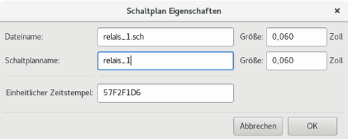
Sie müssen einen Dateinamen eingeben. Wenn es keinen Schaltplannamen gibt dann wird der Dateiname als Blattname verwendet. Dies ist der übliche Weg.
Verbindungen - Hierarchische Verbinder
Hier erstellen Sie die Verbindungspunkte (hierarchische Bezeichner) für das Symbol, das gerade erstellt wurde.
These points of connection are similar to normal symbol pins, with however the possibility to connect a complete bus with only one point of connection.
Es gibt zwei Wege das zu tun:
-
Platzieren Sie die unterschiedlichen Anschlüsse bevor Sie das Unterblatt zeichnen (manuelle Platzierung).
-
Platzieren Sie die unterschiedlichen Anschlüsse nachdem Sie das Unterblatt und die globalen Label gezeichnet haben (halbautomatische Platzierung).
Die zweite Lösung sollte bevorzugt werden.
Manuelle Platzierung:
-
Wählen Sie das Werkzeug
 .
. -
Klicken Sie auf das Hierarchiesymbol an dem Sie diesen Anschluss platzieren möchten.
Sie sehen unten ein Beispiel für die Erstellung eines hierarchischen Anschlusses mit dem Namen "Signaltakt".
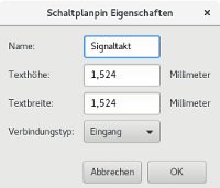
Sie können den Namen, die grafischen Eigenschaften und den Verbindungstyp definieren, oder dies später nachholen indem Sie dieses Anschlussblatt bearbeiten (Rechtsklick und Bearbeiten im Pop-Up Menü).
Auf dem Blatt muss ein Hierarchisches Label vorhanden sein welches den gleichen Namen hat wieder der hierarchische Verbinder. Dabei muss manuell darauf geachtet werden das die zwei Namen sich nicht unterscheiden. Deswegen ist die zweite Lösung, wie nachfolgend beschrieben, die bevorzugte Variante.
Automatische Platzierung:
-
Wählen Sie das Werkzeug
 .
. -
Klicken Sie auf das Hierarchiesymbol von wo Sie die Anschlüsse zum korrespondierenden globalen Label aus dem korrespondierenden Schaltplan importieren wollen. Ein hierarchischer Anschluss erscheint, wenn ein neues globales Label vorhanden ist, welches noch nicht mit einem schon vorhandenen Anschluss verbunden.
-
Klicken Sie dorthin wo Sie diesen Anschluss platzieren wollen.
Alle notwendigen Anschlüsse können so schnell und ohne logische Fehler platziert werden. Ihr Erscheinungsbild entspricht den entsprechenden globalen Labeln.
Verbindungen - Hierarchische Labels
Jede Verbindung, welche auf dem Blattsymbol erstellt worden ist, muss ein korrespondierendes hierarchisches Label im Unterblatt besitzen. Hierarchische Label sind gleich den normalen Labels, verbinden aber als Zusatz zu den normalen Labels das Unterblatt mit dem Hauptblatt und umgekehrt. Die grafische Darstellung der zwei ergänzenden Labels (Verbindung und HLabel) ist gleich. Hierarchische Label werden mit dem Werkzeug ![]() erstellt.
erstellt.
Siehe nachfolgendes Beispiel eines Hauptblattes:
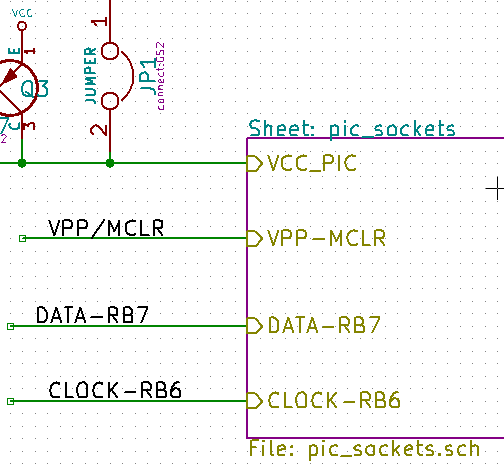
Beachten Sie den Anschluss VCC_PIC, der mit dem Jumper JP1 verbunden ist.
Und dies sind die zugehörigen Verbindungen auf dem Unterblatt:
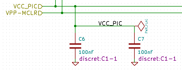
Sie sehen wieder die beiden korrespondierenden hierarchischen Label, die eine Verbindung zwischen den beiden hierarchischen Blättern herstellen.
| Sie können hierarchische Label und hierarchische Anschlüsse verwenden, um zwei Busse zu verbinden, entsprechend der Syntax (Bus[N..m]) wie schon beschrieben (siehe Abschnitt 5.5.3). |
Labels, hierarchische Labels, globale Labels und unsichtbare Spannungsversorgungsanschlüsse
Einige Anmerkungen zu verschiedenen Arten eine Verbindung herzustellen, anders als über durch Leitungen.
Einfache Label
Einfache Label können nur lokale Punkte verbinden, d.h. begrenzt auf das Schaltplanblatt wo diese platziert sind. Das kommt daher da:
-
Jedes Blatt hat eine Blattnummer.
-
Die Blattnummer ist mit dem Label verbunden.
Also, wenn Sie ein Label "TOTO" auf Blatt 3 platzieren, dann ist das tatsächliche Label "TOTO_3". Wenn Sie ein Label "TOTO" ebenfalls auf Blatt 1 (dem Hauptblatt) platzieren, erstellen Sie eigentlich ein Label "TOTO_1" welches sich durch den angehängten Suffix von "TOTO_3" unterscheidet. Dieses Verhalten ist auch gegeben wenn es nur ein Blatt im Projekt gibt.
Hierarchische Label
Was für einfache Label gesagt wurde, gilt auch für hierarchische Label.
Thus in the same sheet, a hierarchical label "TOTO" is considered to be connected to a local label "TOTO", but not connected to a hierarchical label or label called "TOTO" in another sheet.
A hierarchical label is considered to be connected to the corresponding sheet pin symbol in the hierarchical symbol placed in the parent sheet.
Unsichtbare Spannungsanschlüsse
It was seen that invisible power pins were connected together if they have the same name. Thus all the power pins declared "Invisible Power Pins" and named VCC are connected all symbol invisible power pins named VCC only within the sheet they are placed.
Das bedeutet, wenn Sie ein Label "VCC" in einem Unterblatt platzieren, wird es nicht mit VCC Anschlüssen verbunden, weil dieses Label eigentlich VCC_n heißt, wobei n die Blattnummer ist.
If you want this label VCC to be really connected to the VCC for the entire schematic, it will have to be explicitly connected to an invisible power pin via a VCC power symbol.
Globale Label
Globale Label, die einen identischen Namen haben, sind über alle Schaltplanseiten miteinander verbunden.
Label für Spannungen wie VCC, … sind globale Label.
Komplexe Hierarchie
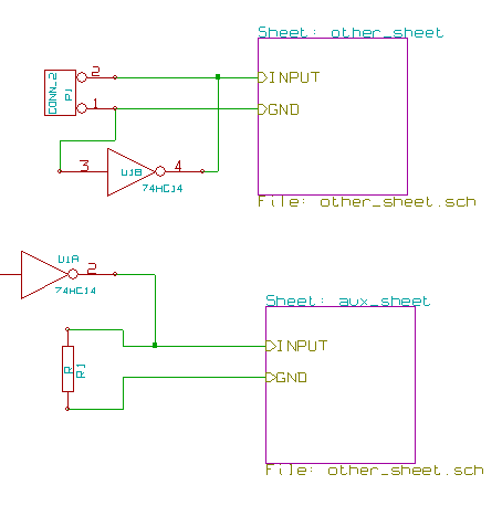
Here is an example. The same schematic is used twice (two instances). The two sheets share the same schematic because the file name is the same for the two sheets (``other_sheet.sch''). The sheet names must be unique.
Flache Hierarchie
You can create a project using many sheets without creating connections between these sheets (flat hierarchy) if the following rules are observed:
-
Create a root sheet containing the other sheets which acts as a link between others sheets.
-
Es werden keine expliziten Verbindungen benötigt.
-
Use global labels instead of hierarchical labels in all sheets.
Hier ist ein Beispiel eines Hauptblattes.
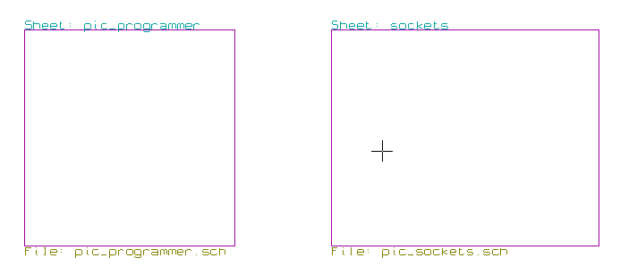
Hier sind die zwei Blätter, verbunden über globale Label.
Dies ist ein Ausschnitt aus dem Schaltplan pic_programmer.sch.
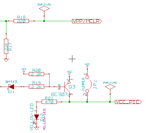
Und der zugehörige Ausschnitt aus pic_sockets.sch.
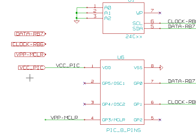
Schauen Sie auf die globalen Labels.
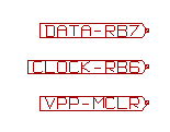
Symbol Annotation Tool
Einleitung
The annotation tool allows you to automatically assign a designator to symbols in your schematic. Annotation of symbols with multiple units will assign a unique suffix to minimize the number of these symbols. The annotation tool is accessible via the icon ![]() . Here you find its main window.
. Here you find its main window.

Available annotation schemes:
-
Annotate all the symbols (reset existing annotation option)
-
Annotate all the symbols, but do not swap any previously annotated multi-unit parts.
-
Annotate only symbols that are currently not annotated. Symbols that are not annotated will have a designator which ends with a '?' character.
-
Ganze Hierarchie annotieren (alle Schaltpläne).
-
Nur aktuelles Blatt annotieren (Nur den gegenwärtigen Schaltplan bearbeiten).
The ``Reset, but do not swap any annotated multi-unit parts'' option keeps all existing associations between symbols with multilple units. For example, U2A and U2B may be reannotated to U1A and U1B respectively but they will never be reannotated to U1A and U2A, nor to U2B and U2A. This is useful if you want to ensure that pin groupings are maintained.
Die Auswahl der Annotationsreihenfolge legt die Methode fest, die verwendet wird um die Referenznummerierung innerhalb jeden Blattes der Hierarchie durchzuführen.
Außer in speziellen Fällen wird eine automatische Beschriftung für das gesamte Projekt (alle Arbeitsblätter) und für alle neuen Bauteile durchgeführt, wenn Sie keine bestehenden Beschriftungen ändern wollen.
The Annotation Choice gives the method used to calculate reference:
-
Use first free number in schematic: components are annotated from 1 (for each reference prefix). If a previous annotation exists, only unused numbers will be used.
-
Verwende erste freie Nummer bis Schaltplannummer x 100: Beschriftung startet von 101 für Blatt 1, und von 201 für Blatt 2, usw. Wenn es mehr als 99 Bauteile mit dem gleichen Referenzpräfix (U, R, …) auf Blatt 1 gibt, wird das Annotierungs-Werkzeug die Nummer 200 und folgende verwenden. Die Beschriftung auf Blatt 2 wird dann mit der nächsten freien Nummer fortgesetzt.
-
Verwende erste freie Nummer bis Schaltplannummer x 1000. Beschriftung startet mit 1001 auf Blatt 1, mit 2001 auf Blatt 2.
Einige Beispiele
Reihenfolge der Annotation
Dieses Beispiel zeigt 5 platzierte Bauteile, die aber noch nicht annotiert worden sind.
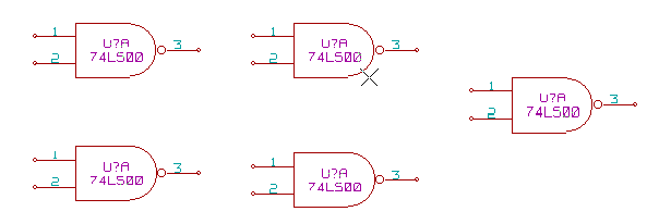
Nachdem das Annotationswerkzeug ausgeführt wurde, erhält man dieses Ergebnis.
Sortiert nach X-Position.

Sortiert nach Y-Position.

Sie können sehen, dass vier 74LS00 Gatter im U1 Bauteil verteilt wurden und das fünfte 74LS00 Gatter wurde dem nächsten Bauteil U2 zugewiesen.
Annotationsauswahl
Hier ist eine Beschriftung in Blatt 2 wo die Option "Verwende erste Nummer im Schaltplan" gesetzt wurde.
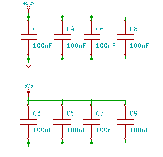
Option "Verwende erste freie Nummer bis Schaltplannummer x 100" ergibt folgendes Ergebnis.
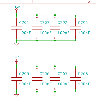
Option "Verwende erste freie Nummer bis Schaltplannummer x 1000" ergibt folgendes Ergebnis.
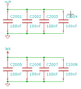
Entwurfsprüfung mit ERC (Elektrische Regel Prüfung)
Einleitung
Das Werkzeug für die elektrische Regel Prüfung (ERC) führt eine automatische Prüfung Ihres Schaltplans durch. Der ERC prüft auf mögliche Fehler in ihrem Schaltplan, wie nicht verbundene Anschlüsse, nicht verbundene hierarchische Symbole, kurzgeschlossene Ausgänge, usw. Naturgemäß ist eine automatische Prüfung nicht unfehlbar und das Programm, das alle Entwurfsfehler erkennen kann ist noch nicht zu 100% fertig gestellt. Solch eine Prüfung ist sehr hilfreich da diese Ihnen hilft, viele versehentliche und kleine Fehler zu finden.
In fact all detected errors must be checked and then corrected before proceeding as normal. The quality of the ERC is directly related to the care taken in declaring electrical pin properties during symbol library creation. ERC output is reported as errors'' or warnings''.

ERC Benutzung
Der ERC kann über klicken auf das Symbol ![]() gestartet werden.
gestartet werden.
Warnungen werden auf den Schaltplanelementen platziert, die einen ERC Fehler verursachen (z.B. Anschlüsse oder Label).
|
Sie können auch Fehlermarkierungen im Dialogfeld löschen.
Beispiel eines ERC mit Fehlern
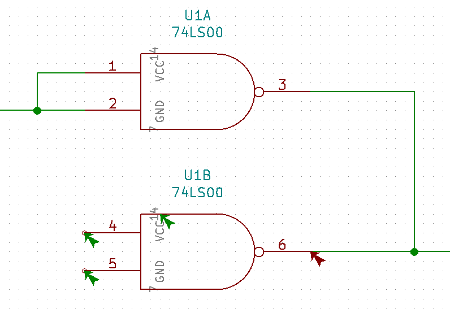
Hier sehen Sie vier Fehler:
-
Zwei Ausgänge wurden fehlerhaft miteinander verbunden (roter Pfeil am Pin 6).
-
Zwei Eingänge wurden offen gelassen (grüner Pfeil an den Pins 4 und 5).
-
Es gibt einen Fehler an einem ausgeblendeten Spannungsanschluss, die Markierung der Spannungsversorgung fehlt (grüner Pfeil am Gatter U1B).
Prüfergebnisse anzeigen
Mit doppelten Linksklick oder bei mehrfachen Auswahlmöglichkeiten unter dem Cursor nach Auswahl der Fehlermarkierung bei einem Rechtsklick zeigt Ihnen das Pop-Up Menü das Prüfergebnis zur Markierung.
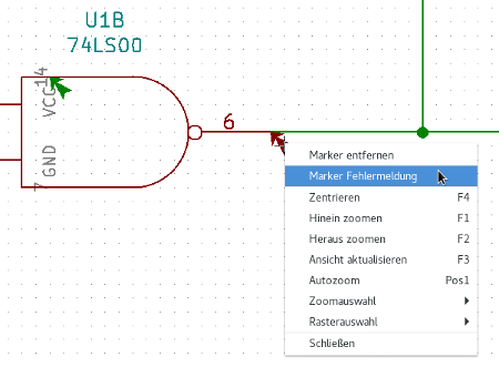
Wenn Sie auf den Marker zur Fehlerinformation klicken, erhalten Sie eine Beschreibung des Fehlers.
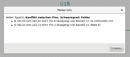
Spannungsversorgungsanschlüsse und Markierungen von Spannungsversorgungen
Es ist nicht unwahrscheinlich einen Fehler oder eine Warnung bei einem ERC für Spannungsversorgungsanschlüsse angezeigt zu bekommen, selbst wenn alles auf den ersten Blick normal aussieht. Sehen Sie sich nochmal das Beispiel oben an. Dies passiert weil in den meisten Entwürfen von Schaltplänen die Spannungsversorgung über Steckverbinder erfolgt, die an sich keine Spannungsquelle sind (anders wie z.B. der Ausgang eines Spannungsreglers, der als Spannungsausgang deklariert ist).
Der ERC wird daher keinen Spannungsausgang finden können der diese Leitung versorgt, und wird die Schaltung als nicht von einer Spannungsquelle versorgt detektieren.
Um diese Warnung zu vermeiden müssen Sie ein "PWR_FLAG" an so eine Spannungsversorgung platzieren. Sehen Sie sich das folgende Beispiel an:
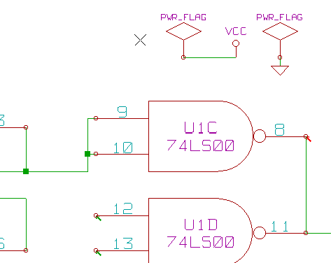
Die Fehlermarkierung wird dann verschwinden.
Most of the time, a PWR_FLAG must be connected to GND, because regulators have outputs declared as power out, but ground pins are never power out (the normal attribute is power in), so grounds never appear connected to a power source without a power flag symbol.
Konfiguration
Im Tab Optionen des geöffneten ERC Dialogs können Sie die Verbindungsregeln einrichten, um die elektrischen Bedingungen für die Prüfungen auf Fehler und Warnungen festzulegen.

Die Regeln können durch Klicken auf das gewünschte Kästchen in der Matrix geändert werden, es wird bei jedem Klick durch die Auswahl mit diesen Optionen fortlaufend iteriert: Normal, Warnung, Fehler.
ERC Protokolldatei
Eine ERC Protokolldatei kann erstellt und abgespeichert werden indem die Option "ERC Protokolldatei erstellen" aktiviert wird. Die Dateiendung für eine ERC Protokolldatei ist .erc. Hier ist ein Beispiel einer ERC Protokolldatei:
ERC control (4/1/1997-14:16:4)

***** Sheet 1 (INTERFACE UNIVERSAL)
ERC: Warning Pin input Unconnected @ 8.450, 2.350
ERC: Warning passive Pin Unconnected @ 8.450, 1.950
ERC: Warning: BiDir Pin connected to power Pin (Net 6) @ 10.100, 3.300
ERC: Warning: Power Pin connected to BiDir Pin (Net 6) @ 4.950, 1.400

>> Errors ERC: 4
Eine Netzliste erzeugen
Überblick
A netlist is a file which describes electrical connections between symbols. These connections are referred to as nets. In the netlist file you can find:
-
The list of the symbols
-
The list of connections (nets) between symbols.
Many different netlist formats exist. Sometimes the symbols list and the list of nets are two separate files. This netlist is fundamental in the use of schematic capture software, because the netlist is the link with other electronic CAD software such as:
-
PCB layout software.
-
Schematic and electrical signal simulators.
-
Compiler für CPLD’s (und andere programmierbare Bausteine).
Eeschema unterstützt folgende Netzlistenformate:
-
Pcbnew Format (Leiterplatten).
-
ORCAD PCB2 Format (Leiterplatten).
-
CADSTAR Format (Leiterplatten).
-
Spice Format, für verschiedene Simulatoren (das Spice-Format wird ebenfalls von anderen Simulatoren verwendet).
Netzlistenformate
Select the tool ![]() to open the netlist creation dialog.
to open the netlist creation dialog.
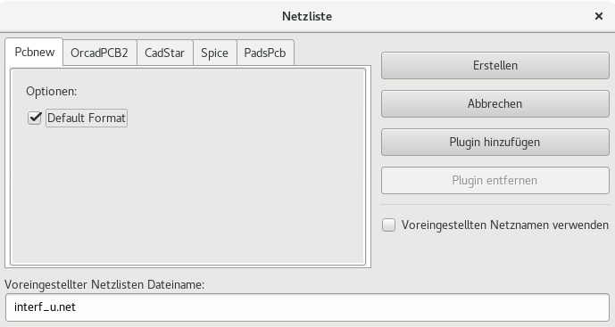
Reiter Pcbnew ausgewählt
Reiter Spice ausgewählt
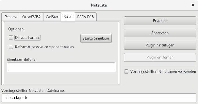
Using the different tabs you can select the desired format. In Spice format you can generate netlists with either net names which makes the SPICE file more human readable or net numbers which are used by older Spice. By clicking the Netlist button, you will be asked for a netlist file name.
| The netlist generation can take up to several minutes for large schematics. |
Beispiele für Netzlisten
Nachfolgend sehen Sie einen Schaltplanentwurf unter Nutzung der PSPICE Bibliothek:
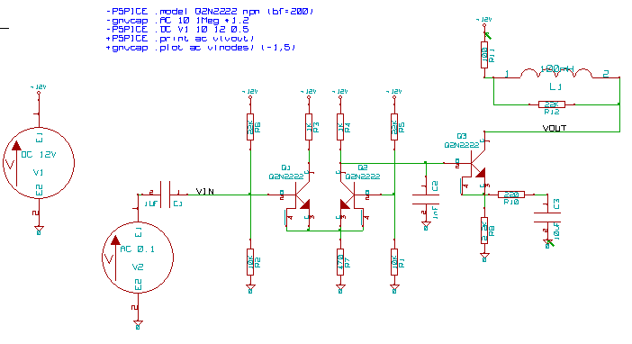
Beispiel einer Pcbnew Netzlistendatei:
# Eeschema Netlist Version 1.0 generee le 21/1/1997-16:51:15
(
(32E35B76 $noname C2 1NF {Lib=C}
(1 0)
(2 VOUT_1)
)
(32CFC454 $noname V2 AC_0.1 {Lib=VSOURCE}
(1 N-000003)
(2 0)
)
(32CFC413 $noname C1 1UF {Lib=C}
(1 INPUT_1)
(2 N-000003)
)
(32CFC337 $noname V1 DC_12V {Lib=VSOURCE}
(1 +12V)
(2 0)
)
(32CFC293 $noname R2 10K {Lib=R}
(1 INPUT_1)
(2 0)
)
(32CFC288 $noname R6 22K {Lib=R}
(1 +12V)
(2 INPUT_1)
)
(32CFC27F $noname R5 22K {Lib=R}
(1 +12V)
(2 N-000008)
)
(32CFC277 $noname R1 10K {Lib=R}
(1 N-000008)
(2 0)
)
(32CFC25A $noname R7 470 {Lib=R}
(1 EMET_1)
(2 0)
)
(32CFC254 $noname R4 1K {Lib=R}
(1 +12V)
(2 VOUT_1)
)
(32CFC24C $noname R3 1K {Lib=R}
(1 +12V)
(2 N-000006)
)
(32CFC230 $noname Q2 Q2N2222 {Lib=NPN}
(1 VOUT_1)
(2 N-000008)
(3 EMET_1)
)
(32CFC227 $noname Q1 Q2N2222 {Lib=NPN}
(1 N-000006)
(2 INPUT_1)
(3 EMET_1)
)
)
# End
Im PSPICE-Format sieht die Netzliste wie folgt aus:
* Eeschema Netlist Version 1.1 (Spice format) creation date: 18/6/2008-08:38:03

.model Q2N2222 npn (bf=200)
.AC 10 1Meg \*1.2
.DC V1 10 12 0.5


R12   /VOUT N-000003 22K
R11   +12V N-000003 100
L1   N-000003 /VOUT 100mH
R10   N-000005 N-000004 220
C3   N-000005 0 10uF
C2   N-000009 0 1nF
R8   N-000004 0 2.2K
Q3   /VOUT N-000009 N-000004 N-000004 Q2N2222
V2   N-000008 0 AC 0.1
C1   /VIN N-000008 1UF
V1   +12V 0 DC 12V
R2   /VIN 0 10K
R6   +12V /VIN 22K
R5   +12V N-000012 22K
R1   N-000012 0 10K
R7   N-000007 0 470
R4   +12V N-000009 1K
R3   +12V N-000010 1K
Q2   N-000009 N-000012 N-000007 N-000007 Q2N2222
Q1   N-000010 /VIN N-000007 N-000007 Q2N2222

.print ac v(vout)
.plot ac v(nodes) (-1,5)

.end
Anmerkungen zu Netzlisten
Zu beachtende Punkte für die Benennung von Netzlisten
Many software tools that use netlists do not accept spaces in the component names, pins, nets or other informations. Avoid using spaces in labels, or names and value fields of components or their pins to ensure maximum compatibility.
In der gleichen Weise können spezielle Zeichen, die keine Buchstaben oder Zahlen sind, Probleme verursachen. Beachten Sie, dass diese Einschränkung nicht für Eeschema gilt, sondern für Netzlistenformate, die dann nicht übersetzbar sind für Software, die Netzlistendateien verwendet.
PSPICE Netzlisten
Für den Pspice Simulator müssen Sie einige Befehlszeilen in der Netzliste selbst einfügen (.PROBE, .AC, etc.).
Jede Textzeile, die im Schaltplan einfügt wird und mit den Schlüsselwörtern -pspice oder -gnucap beginnt, wird (ohne das Schlüsselwort) am Anfang der Netzliste eingefügt.
Jede Textzeile, die im Schaltplan einfügt wird und mit den Schlüsselwörtern +pspice oder +gnucap beginnt, wird (ohne das Schlüsselwort) am Ende der Netzliste eingefügt.
Hier ist ein Beispiel das viele einzeilige Texte und einen mehrzeiligen Text verwendet:
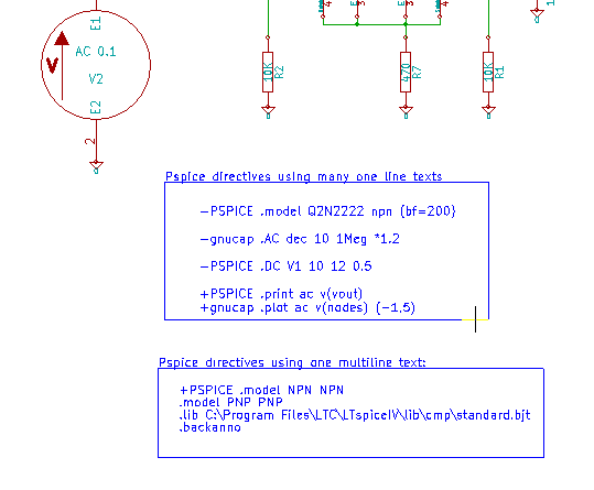
Zum Beispiel, wenn Sie folgenden Text eingeben (Verwenden Sie kein Label!):
-PSPICE .PROBE
wird eine Zeile .PROBE in die Netzliste eingefügt.
Im vorherigen Beispiel oben wurden mit dieser Technik drei Zeilen am Anfang der Netzliste eingefügt und zwei am Ende.
Wenn Sie mehrzeiligen Text verwenden werden die +pspice oder +gnucap Schlüsselwörter nur einmal benötigt:
+PSPICE .model NPN NPN
.model PNP PNP
.lib C:\Program Files\LTC\LTspiceIV\lib\cmp\standard.bjt
.backanno
erzeugt diese vier Zeilen:
.model NPN NPN
.model PNP PNP
.lib C:\Program Files\LTC\LTspiceIV\lib\cmp\standard.bjt
.backanno
Also note that the GND net must be named 0 (zero) for Pspice.
Andere Formate
Für andere Netzlistenformate können Sie Netzlistenkonverter in Form von Plugins hinzufügen. Diese Konverter werden automatisch von Eeschema gestartet. Kapitel 14 zeigt einige Erklärungen und Beispiele für Konverter.
Ein Konverter ist eine Textdatei (XSL-Format), aber Sie können auch andere Sprachen wie Python verwenden. Wenn Sie das XSL-Format verwenden, liest ein Werkzeug (xsltproc.exe unter Windows oder xsltproc unter Linux/MAC) das Zwischenformat und die Konverterdatei, welches von Eeschema erzeugt wird, um die Ausgabedatei zu erzeugen. In diesem Fall ist die Konverterdatei (ein Stylesheet) sehr klein und leicht zu schreiben.
Das Dialogfenster aufrufen
Sie können ein neues Netzlisten-Plugin über den Button ``Plugin hinzufügen'' einzufügen.
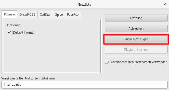
Hier ist das Setup-Fenster für das PadsPcb Plugin zu sehen:
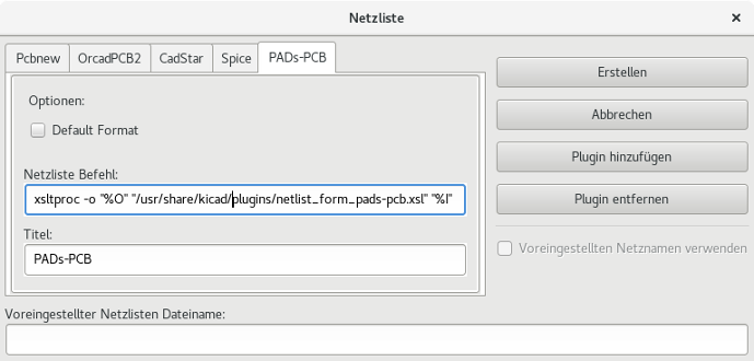
Das Setup benötigt:
-
Einen Titel (zum Beispiel der Name für das Netzlistenformat).
-
Das zu startende Plugin.
Wenn die Netzliste erzeugt wurde:
-
Eeschema erzeugt eine Zwischendatei *.tmp, zum Beispiel test.tmp.
-
Eeschema startet das Plugin, welches test.tmp liest und test.net erzeugt.
Befehlszeilenformat
Hier ist ein Beispiel, das xsltproc.exe als Werkzeug (unter Windows) verwendet um .xsl Dateien umzuwandeln, und eine Datei netlist_form_pads-pcb.xsl als Konverter Stylesheet benutzt:
f:/kicad/bin/xsltproc.exe -o %O.net f:/kicad/bin/plugins/netlist_form_pads-pcb.xsl %I
Folgende Erläuterungen dazu:
| f:/kicad/bin/xsltproc.exe | A tool to read and convert xsl file |
|---|---|
-o %O.net |
Output file: %O will define the output file. |
f:/kicad/bin/plugins/netlist_form_pads-pcb.xsl |
File name converter (a sheet style, xsl format). |
%I |
Will be replaced by the intermediate file created by Eeschema (*.tmp). |
Für einen Schaltplan mit dem Namen test.sch, wäre die tatsächliche Befehlszeile:
f:/kicad/bin/xsltproc.exe -o test.net f:/kicad/bin/plugins/netlist_form_pads-pcb.xsl test.tmp.
Konverter und Stylesheet (Plugin)
Dies ist ein sehr einfaches Stück Software, da sein einziger Zweck ist, eine Textdatei (die Zwischendatei) in eine andere Datei umzuwandeln. Zusätzlich können Sie aus der Zwischendatei auch eine Stückliste (BOM) erstellen.
Wenn Sie nur xsltproc als Konverter verwenden, wird nur das Stylesheet erzeugt.
Dateiformat der Zwischen-Netzliste
Bitte schauen Sie in Kapitel 14 für weitere Erklärungen zu xslproc, Beschreibungen zum Zwischendateiformat und einigen Beispielen für Stylesheets für Konverter.
Plotten und Drucken
Einleitung
Sie können auf die Druck- und Plotbefehle über das Menü "Datei" zugreifen.
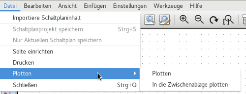
Die unterstützten Ausgabeformate sind Postscript, PDF, SVG, DXF und HPGL. Sie können natürlich ebenfalls auch direkt auf Ihren Drucker drucken.
Übliche Druckbefehle:
- Aktuelle Seite drucken
-
Druckt eine Datei nur für das aktuelle Arbeitsblatt.
- Alle Seiten drucken
-
Erlaubt es Ihnen die ganze Hierarchie auszudrucken (für jedes Arbeitsblatt wird eine Druckdatei erzeugt).
Ausgabe nach Postscript
Dieser Befehl erlaubt es Ihnen Postscriptdateien zu erzeugen.
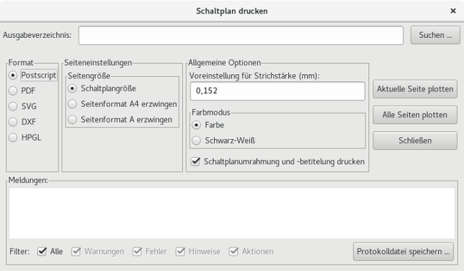
Der Dateiname ist der des Schaltplans mit der Erweiterung .ps. Sie können die Option "Schaltplanumrahmung und -betitelung drucken" abwählen. Das ist hilfreich, wenn Sie eine gekapselte Postscriptdatei erzeugen wollen (Dateiformat .eps), wie es häufig verwendet wird um Diagramme in einer Textverarbeitungssoftware einzufügen. Das Benachrichtigungsfenster zeigt den Dateinamen der erzeugten Datei.
Ausgabe nach PDF
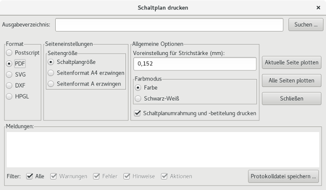
Erlaubt es Ihnen Druckdateien im PDF Format zu erstellen. Der Dateiname ist der Schaltplanname mit der Erweiterung .pdf.
Ausgabe nach SVG
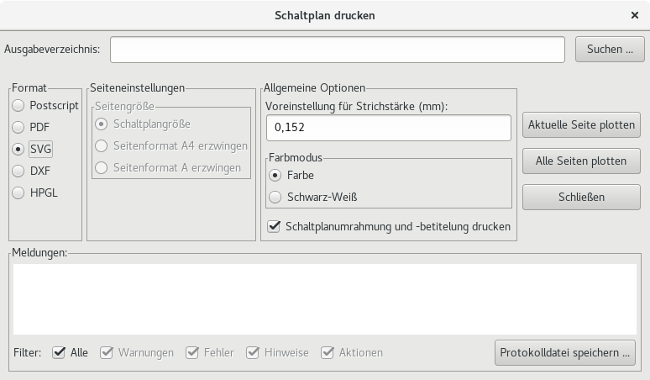
Erlaubt es Ihnen Druckdateien im vektorisierten SVG Format zu erstellen. Der Dateiname ist der Blattname mit der Erweiterung .svg.
Ausgabe nach DXF
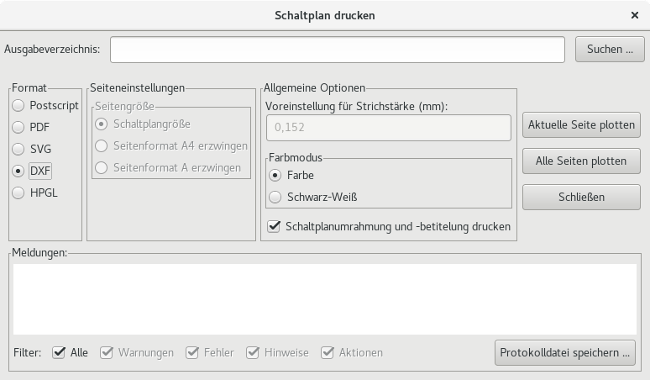
Erlaubt es Ihnen Druckdateien im DXF Format zu erstellen. Der Dateiname ist der Blattname mit der Erweiterung .dxf.
Ausgabe nach HPGL
Dieser Befehl erlaubt es Ihnen eine HPGL Datei zu erstellen. In diesem Format können Sie festlegen:
-
Blattgröße
-
(Koordinaten-)Ursprung
-
Stiftdicke in mm.
Das Dialogfenster der Plottereinstellungen sieht wie folgt aus:
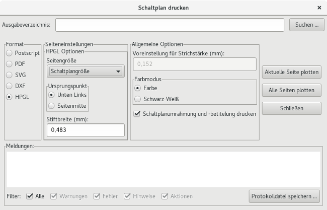
Die Ausgabedatei wird den Schaltplannamen plus die Erweiterung .plt haben.
Auswahl der Seitengröße
Die Seitengröße ist normalerweise auf die Schaltplangröße gesetzt. In diesem Fall wird die im Titelblock festgelegte Blattgröße verwendet und der gewählte Maßstab wird 1:1 sein. Wenn eine andere Blattgröße ausgewählt wird (A4 bis A0 oder A bis E) wird der Maßstab automatisch angepasst, um die Seite zu füllen.
Offset Anpassungen
Für alle Standardabmessungen können Sie den Offset anpassen, um die Zeichnung so präzise wie möglich zu zentrieren. Weil Plotter ihren (Koordinaten-)Ursprung in der Mitte oder in der unteren linken Ecke des Blattes haben, ist es notwendig einen Ursprung festzulegen, um korrekt drucken zu können.
Allgemein ausgedrückt:
-
Für Plotter, die ihren Koordinatenursprung in der Mitte des Blattes haben, muss der Offset negativ sein und auf die Hälfte der Blattabmessungen gesetzt werden.
-
Für Plotter die ihren Koordinatenursprung an der unteren linken Ecke haben muss der Offset auf 0 gesetzt werden.
Um einen Offset einzustellen:
-
Wählen Sie die Blattgröße.
-
Setzen Sie den Offset X und Offset Y.
-
Klicken Sie auf Offset übernehmen.
Drucken auf Papier
Dieser Befehl, verfügbar durch das Icon ![]() , erlaubt es Ihnen, Entwurfsdateien für den Standarddrucker anzuzeigen und zu erzeugen.
, erlaubt es Ihnen, Entwurfsdateien für den Standarddrucker anzuzeigen und zu erzeugen.
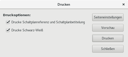
Die Option "Drucke Schaltplanreferenz und Schaltplanbetitelung" schaltet Blattreferenzen und Titelblock ein oder aus.
Die Option "Drucke Schwarz-Weiß" setzt den einfarbigen Druckmodus. Diese Option wird allgemein benötigt wenn sie einen Schwarzweiß Laserdrucker verwenden, weil sonst Farben in Halbtönen ausgegeben werden und häufig nicht gut lesbar sind.
Symbol Library Editor
General Information About Symbol Libraries
A symbol is a schematic element which contains a graphical representation, electrical connections, and fields defining the symbol. Symbols used in a schematic are stored in symbol libraries. Eeschema provides a symbol library editing tool that allows you to create libraries, add, delete or transfer symbols between libraries, export symbols to files, and import symbols from files. The library editing tool provides a simple way to manage symbol library files.
Symbol Library Overview
A symbol library is composed of one or more symbols. Generally the symbols are logically grouped by function, type, and/or manufacturer.
A symbol is composed of:
-
Grafischen Elementen wie Linien, Kreise, Bögen, Text, usw., die die Symboldarstellung festlegen.
-
Anschlüssen (Pins) welche sowohl grafische Eigenschaften haben (Linien, Takt, Invertiert, Low-aktiv, usw.) als auch elektrische Eigenschaften (Eingang, Ausgang, Bidirektional, usw.), die vom ERC-Werkzeug genutzt werden.
-
Feldern für die Referenz, den Wert, zugehörige Footprintnamen für Leiterplattenentwurf, usw.
-
Aliases used to associate a common symbol such as a 7400 with all of its derivatives such as 74LS00, 74HC00, and 7437. All of these aliases share the same library symbol.
Proper symbol designing requires:
-
Defining if the symbol is made up of one or more units.
-
Defining if the symbol has an alternate body style also known as a De Morgan representation.
-
Dem Entwerfen seiner grafischen Darstellung mit Linien, Rechtecken, Kreisen, Polygonen und Text.
-
Das Hinzufügen von Anschlüssen (Pins) unter sorgfältiger Festlegung der grafischen Elemente jedes Anschlusses, des Namens, der Nummer und der elektrischen Eigenschaften (Eingang, Ausgang, Tri-State, Spannungsausgang, usw.).
-
Adding an alias if other symbols have the same design and pin out or removing one if the symbol has been created from another symbol.
-
Das Ergänzen von optionalen Feldern, wie der Name des Footprints, der für den Leiterplattenentwurf verwendet werden soll, und/oder die Festlegung ihrer Sichtbarkeit (im Schaltplan).
-
Documenting the symbol by adding a description string and links to data sheets, etc.
-
Das Abspeichern des Bauteils in der gewünschten Bibliothek.
Symbol Library Editor Overview
The symbol library editor main window is shown below. It consists of three tool bars for quick access to common features and a symbol viewing/editing area. Not all commands are available on the tool bars but can be accessed using the menus.
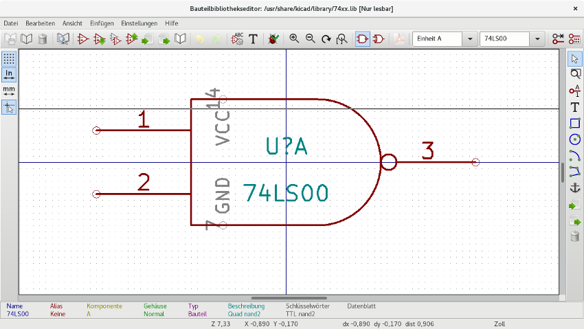
Hauptwerkzeugleiste
The main tool bar typically located at the top of the main window shown below consists of the library management tools, undo/redo commands, zoom commands, and symbol properties dialogs.

|
Save the currently selected library. The button will be disabled if no library is currently selected or no changes to the currently selected library have been made. |
|
Select the library to edit. |
|
Delete a symbol from the currently selected library or any library defined by the project if no library is currently selected. |
|
Open the symbol library browser to select the library and symbol to edit. |
|
Create a new symbol. |
|
Load symbol from currently selected library for editing. |
|
Create a new symbol from the currently loaded symbol. |
|
Save the current symbol changes in memory. The library file is not changed. |
|
Import one symbol from a file. |
|
Export the current symbol to a file. |
|
Create a new library file containing the current symbol. Note: new libraries are not automatically added to the project. |
|
Undo last edit. |
|
Redo last undo. |
|
Edit the current symbol properties. |
|
Edit the fields of current symbol. |
|
Test the current symbol for design errors. |
|
Zoom in. |
|
Zoom out. |
|
Refresh display. |
|
Zoom to fit symbol in display. |
|
Select the normal body style. The button is disabled if the current symbol does not have an alternate body style. |
|
Select the alternate body style. The button is disabled if the current symbol does not have an alternate body style. |
|
Show the associated documentation. The button will be disabled if no documentation is defined for the current symbol. |
|
Select the unit to display. The drop down control will be disabled if the current symbol is not derived from multiple units. |
|
Select the alias. The drop down control will be disabled if the current symbol does not have any aliases. |
|
Pin editing: independent editing for pin shape and position for symbols with multiple units and alternate symbols. |
|
Show pin table. |
Werkzeugleiste Elemente
The vertical toolbar typically located on the right hand side of the main window allows you to place all of the elements required to design a symbol. The table below defines each toolbar button.
|
Select tool. Right-clicking with the select tool opens the context menu for the object under the cursor. Left-clicking with the select tool displays the attributes of the object under the cursor in the message panel at the bottom of the main window. Double-left-clicking with the select tool will open the properties dialog for the object under the cursor. |
|
Pin tool. Left-click to add a new pin. |
|
Graphical text tool. Left-click to add a new graphical text item. |
|
Rectangle tool. Left-click to begin drawing the first corner of a graphical rectangle. Left-click again to place the opposite corner of the rectangle. |
|
Circle tool. Left-click to begin drawing a new graphical circle from the center. Left-click again to define the radius of the circle. |
|
Arc tool. Left-click to begin drawing a new graphical arc item from the center. Left-click again to define the first arc end point. Left-click again to define the second arc end point. |
|
Polygon tool. Left-click to begin drawing a new graphical polygon item in the current symbol. Left-click for each addition polygon line. Double-left-click to complete the polygon. |
|
Anchor tool. Left-click to set the anchor position of the symbol. |
|
Import a symbol from a file. |
|
Export the current symbol to a file. |
|
Delete tool. Left-click to delete an object from the current symbol. |
Werkzeugleiste für Einstellungen
Die linke Werkzeugleiste erlaubt es Ihnen einige Zeichnungseinstellungen für den Editor zu ändern. Die Tabelle unten erklärt jeden Button der Werkzeugleiste.
|
Toggle grid visibility on and off. |
|
Set units to inches. |
|
Set units to millimeters. |
|
Toggle full screen cursor on and off. |
Bibliotheksauswahl und Bibliothekswartung
The selection of the current library is possible via the ![]() which shows you all available libraries and allows you to select one. When a symbol is loaded or saved, it will be put in this library. The library name of symbol is the contents of its value field.
which shows you all available libraries and allows you to select one. When a symbol is loaded or saved, it will be put in this library. The library name of symbol is the contents of its value field.
|
Select and Save a Symbol
When you edit a symbol you are not really working on the symbol in its library but on a copy of it in the computer’s memory. Any edit action can be undone easily. A symbol may be loaded from a local library or from an existing symbol.
Symbol Selection
Clicking the ![]() on the main tool bar displays the list of the available symbols that you can select and load from the currently selected library.
on the main tool bar displays the list of the available symbols that you can select and load from the currently selected library.
If a symbol is selected by its alias, the name of the loaded symbol is displayed on the window title bar instead of the selected alias. The list of symbol aliases is always loaded with each symbol and can be edited. You can create a new symbol by selecting an alias of the current symbol from the  . The first item in the alias list is the root name of the symbol. . The first item in the alias list is the root name of the symbol.
|
|
Alternatively, clicking the |
Save a Symbol
After modification, a symbol can be saved in the current library, in a new library, or exported to a backup file.
To save the modified symbol in the current library, click the ![]() . Please note that the update command only saves the symbol changes in the local memory. This way, you can make up your mind before you save the library.
. Please note that the update command only saves the symbol changes in the local memory. This way, you can make up your mind before you save the library.
To permanently save the symbol changes to the library file, click the ![]() which will overwrite the existing library file with the symbol changes.
which will overwrite the existing library file with the symbol changes.
If you want to create a new library containing the current symbol, click the ![]() . You will be asked to enter a new library name.
. You will be asked to enter a new library name.
|
Neue Bibliotheken werden nicht automatisch dem aktuellen Projekt hinzugefügt. You must add any new library you wish to use in a schematic to the list of project libraries in Eeschema using the Symbol Library Table dialog. |
Click the ![]() to create a file containing only the current symbol. This file will be a standard library file which will contain only one symbol. This file can be used to import the symbol into another library. In fact, the create new library command and the export command are basically identical.
to create a file containing only the current symbol. This file will be a standard library file which will contain only one symbol. This file can be used to import the symbol into another library. In fact, the create new library command and the export command are basically identical.
Transfer Symbols to Another Library
You can very easily copy a symbol from a source library into a destination library using the following commands:
-
Wählen Sie die Quellbibliothek mit einem Klick auf
 .
. -
Load the symbol to be transferred by clicking the
 . The symbol will be displayed in the editing area.
 -
Wählen Sie die Zielbibliothek mit Klick auf
 .
. -
Save the current symbol to the new library in the local memory by clicking the
 .
. -
Save the symbol in the current local library file by clicking the
 .
.
Discarding Symbol Changes
When you are working on a symbol, the edited symbol is only a working copy of the actual symbol in its library. This means that as long as you have not saved it, you can just reload it to discard all changes made. If you have already updated it in the local memory and you have not saved it to the library file, you can always quit and start again. Eeschema will undo all the changes.
Creating Library Symbols
Create a New Symbol
A new symbol can be created by clicking the ![]() . You will be asked for a symbol name (this name is used as default value for the value field in the schematic editor), the reference designator (U, IC, R…), the number of units per package (for example a 7400 is made of 4 units per package) and if an alternate body style (sometimes referred to as DeMorgan) is desired. If the reference designator field is left empty, it will default to "U". These properties can be changed later, but it is preferable to set them correctly at the creation of the symbol.
. You will be asked for a symbol name (this name is used as default value for the value field in the schematic editor), the reference designator (U, IC, R…), the number of units per package (for example a 7400 is made of 4 units per package) and if an alternate body style (sometimes referred to as DeMorgan) is desired. If the reference designator field is left empty, it will default to "U". These properties can be changed later, but it is preferable to set them correctly at the creation of the symbol.
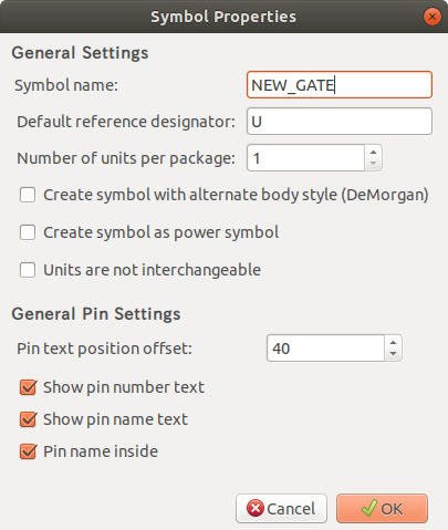
A new symbol will be created using the properties above and will appear in the editor as shown below.
Create a Symbol from Another Symbol
Often, the symbol that you want to make is similar to one already in a symbol library. In this case it is easy to load and modify an existing symbol.
-
Load the symbol which will be used as a starting point.
-
Click on the
 or modify its name by right-clicking on the value field and editing the text. If you chose to duplicate the current symbol, you will be prompted for a new symbol name.
 -
If the model symbol has aliases, you will be prompted to remove aliases from the new symbol which conflict with the current library. If the answer is no the new symbol creation will be aborted. Symbol libraries cannot have any duplicate names or aliases.
-
Edit the new symbol as required.
-
Update the new symbol in the current library by clicking the
 or save to a new library by clicking the
  or if you want to save this new symbol in an other existing library select the other library by clicking on the
  and save the new symbol.
 -
Speichern Sie die aktuelle Bibliotheksdatei auf die Festplatte mit Klick auf
 .
.
Symbol Properties
Symbol properties should be carefully set during the symbol creation or alternatively they are inherited from the copied symbol. To change the symbol properties, click on the ![]() to show the dialog below.
to show the dialog below.
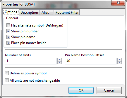
Es ist sehr wichtig die Anzahl der Einheiten pro Bauteil korrekt zu setzen und ob das Bauteil eine alternative Darstellung hat, denn wenn Anschlüsse bearbeitet oder erstellt werden, werden die entsprechenden Pins für jede Einheit erstellt. Wenn Sie die Anzahl der Einheiten pro Bauteil nach der Erstellung und Bearbeitung der Anschlüsse ändern, wird zusätzliche Arbeit notwendig um die neuen Anschlüsse und Symbole der Einheiten zu erstellen. Nichtsdestotrotz ist es möglich diese Eigenschaften zu jeder Zeit zu ändern.
The graphic options "Show pin number" and "Show pin name" define the visibility of the pin number and pin name text. This text will be visible if the corresponding options are checked. The option "Place pin names inside" defines the pin name position relative to the pin body. This text will be displayed inside the symbol outline if the option is checked. In this case the "Pin Name Position Offset" property defines the shift of the text away from the body end of the pin. A value from 30 to 40 (in 1/1000 inch) is reasonable.
The example below shows a symbol with the "Place pin name inside" option unchecked. Notice the position of the names and pin numbers.
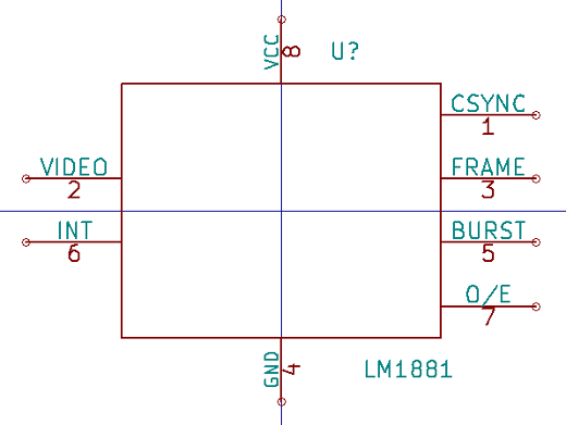
Symbols with Alternate Symbolic Representation
If the symbol has more than one symbolic repersentation, you will have to select one representation to edit them. To edit the normal representation, click the ![]() .
.
To edit the alternate representation, click on the ![]() . Use the
. Use the  shown below to select the unit you wish to edit.
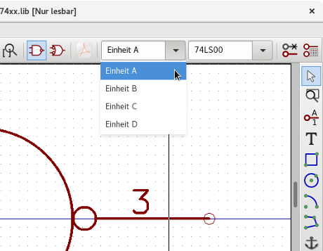
Grafische Elemente
Graphical elements create the representation of a symbol and contain no electrical connection information. Their design is possible using the following tools:
-
Linien und Polygone, die durch Anfangs- und Endpunkte definiert sind.
-
Rechtecke, die durch zwei diagonale Ecken definiert sind.
-
Kreise, die durch Zentrum und Radius definiert sind.
-
Kreisbögen, die durch den Anfangs- und Endpunkt des Bogens und sein Zentrum definiert sind. Ein Kreisbogen geht von 0° bis 180°.
The vertical toolbar on the right hand side of the main window allows you to place all of the graphical elements required to design the representation of a symbol.
Zugehörigkeit grafischer Elemente
Jedes grafische Element (Linie, Kreis Kreisbogen, usw.) kann als zugehörig zu allen Einheiten und/oder Bauform oder speziell für eine Einheit und/oder Bauform definiert werden. Elementeigenschaften können einfach und schnell über das Kontextmenü durch einen Rechtsklick auf das ausgewählte Element ausgewählt werden. Unten sehen Sie das Kontextmenü für ein Linienelement.
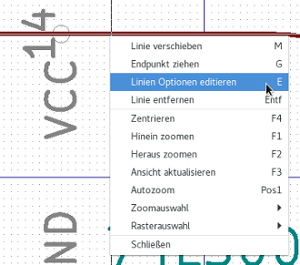
Sie können ebenfalls auf ein Element doppelklicken, um seine Eigenschaften zu bearbeiten. Unten ist der Eigenschaftendialog für die Eigenschaften eines Linienzuges zu sehen
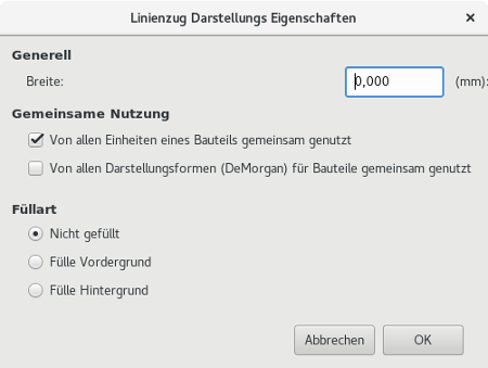
Die Eigenschaften eines grafischen Elementes sind:
-
Breite, definiert die Strichbreite des Elements in der aktuellen Maßeinheit.
-
The "Common to all units in symbol" setting defines if the graphical element is drawn for each unit in symbol with more than one unit per package or if the graphical element is only drawn for the current unit.
-
The "Common by all body styles (DeMorgan)" setting defines if the graphical element is drawn for each symbolic representation in symbols with an alternate body style or if the graphical element is only drawn for the current body style.
-
Die Einstellung der Füllart legt fest ob das Symbol, das mit diesem grafischen Element dargestellt wird, ungefüllt, mit gefülltem Hintergrund oder gefülltem Vordergrund gezeichnet wird.
Grafische Textelemente
The ![]() allows for the creation of graphical text. Graphical text is always readable, even when the symbol is mirrored. Please note that graphical text items are not fields.
allows for the creation of graphical text. Graphical text is always readable, even when the symbol is mirrored. Please note that graphical text items are not fields.
Multiple Units per Symbol and Alternate Body Styles
Symbols can have two symbolic representations (a standard symbol and an alternate symbol often referred to as "DeMorgan") and/or have more than one unit per package (logic gates for example). Some symbols can have more than one unit per package each with different symbols and pin configurations.
Consider for instance a relay with two switches which can be designed as a symbol with three different units: a coil, switch 1, and switch 2. Designing a symbol with multiple units per package and/or alternate body styles is very flexible. A pin or a body symbol item can be common to all units or specific to a given unit or they can be common to both symbolic representation so are specific to a given symbol representation.
Standardmäßig sind Anschlüsse spezifisch für jede Darstellungsform in jeder Einheit, weil die Anschlussnummer speziell für dieser Einheiten gilt und die Form von der Darstellungsform abhängt. Wenn ein Anschluss für alle Einheiten und Darstellungsformen gemeinsam gilt, müssen Sie es nur einmal für alle Einheiten und Darstellungsformen erstellen (das ist üblicherweise der Fall für Spannungsanschlüsse). Das trifft ebenfalls auf die grafischen Elemente der Darstellungsform zu, welche gemeinsam für alle Einheiten gültig sein können (aber typischerweise speziell für jede einzelne Darstellungsform sind).
Example of a Symbol Having Multiple Units with Different Symbols:
Das ist ein Beispiel eines Relais das mit drei Einheiten pro Bauteil definiert wurde, Wechsler 1, Wechsler 2 und Spule:
Option: Anschlüsse sind nicht verbunden. Sie können Anschlüsse für jede Einheit hinzufügen oder bearbeiten ohne Verknüpfung zu Anschlüssen der anderen Einheiten.

"Untereinander nicht austauschbare Einheiten" muss aktiviert sein.
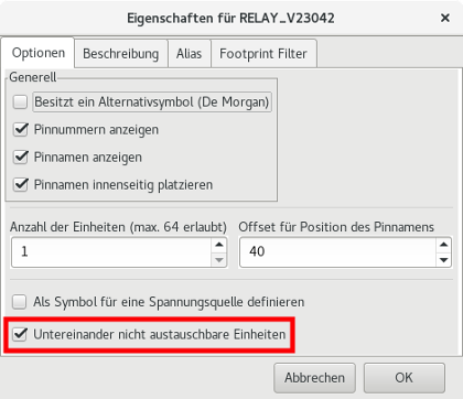
Einheit 1
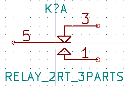
Einheit 2
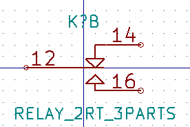
Einheit 3
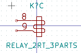
Diese Einheit hat nicht das gleiche Symbol und Anschlusslayout und ist daher nicht austauschbar mit den Einheiten 1 und 2.
Grafische Symbolelemente
Shown below are properties for a graphic body element. From the relay example above, the three units have different symbolic representations. Therefore, each unit was created separately and the graphical body elements must have the "Common to all units in symbol" disabled.
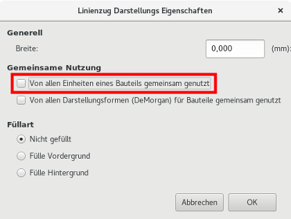
Anschlusserstellung und Anschlussbearbeitung
Sie können auf ![]() klicken um einen Anschluss zu erstellen und einzufügen. Das Bearbeiten aller Anschlusseigenschaften wird aufgerufen durch einen Doppelklick auf den Anschluss oder Rechtsklick auf den Anschluss um das Kontextmenü zu öffnen. Anschlüsse müssen sorgfältig erstellt werden, jeder Fehler einen Einfluss auf den Leiterplattenentwurf hat. Schon vorhandene Anschlüsse können bearbeitet, gelöscht und/oder bewegt werden.
klicken um einen Anschluss zu erstellen und einzufügen. Das Bearbeiten aller Anschlusseigenschaften wird aufgerufen durch einen Doppelklick auf den Anschluss oder Rechtsklick auf den Anschluss um das Kontextmenü zu öffnen. Anschlüsse müssen sorgfältig erstellt werden, jeder Fehler einen Einfluss auf den Leiterplattenentwurf hat. Schon vorhandene Anschlüsse können bearbeitet, gelöscht und/oder bewegt werden.
Anschlussübersicht
Ein Anschluss ist über seine grafische Darstellung, seinen Namen und seine "Nummer" definiert. Die "Nummer" des Anschlusses ist über 4 Zeichen (Buchstaben und/oder Nummern) festgelegt. Damit das ERC-Werkzeug nutzbringend ist, muss der Elektrische Typ des Anschlusses (Eingang, Ausgang, Tri-State, …) korrekt festgelegt sein. Wenn der Typ nicht korrekt gesetzt ist, können die Prüfergebnisse des ERC falsch sein.
Wichtige Hinweise:
-
Verwenden Sie keine Leerzeichen in den Anschlussnamen und Anschlussnummern.
-
Um einen Anschlussnamen mit einem invertierten Signal zu definieren (Überstrich) benutzen Sie das
~(Tilde) Zeichen. Das nächste~Zeichen wird den Überstrich beenden. Zum BeispielFOOwird dargestellt als FO O. -
Ist der Anschlussname auf ein einziges Zeichen reduziert wird der Anschluss als nicht benannt betrachtet.
-
Anschlussnamen die mit
#beginnen, sind für Symbole vom Typ Spannungsanschluss reserviert. -
Eine Anschluss-"Nummer" besteht aus 1 bis 4 Buchstaben und/oder Nummern. 1,2,..9999 sind gültige Nummern. A1, B3, Anod, Gnd, Wire, usw. sind ebenfalls gültig.
-
Duplicate pin "numbers" cannot exist in a symbol.
Anschlusseigenschaften
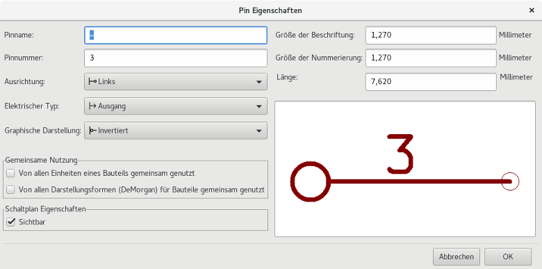
Der Dialog der Anschlusseigenschaften erlaubt es Ihnen alle Eigenschaften eines Anschlusses, auch Pin genannt, zu bearbeiten. Dieser Dialog wird automatisch geöffnet, wenn Sie einen Anschluss erstellen oder auf einen vorhandenen Anschluss doppelklicken. Dieser Dialog erlaubt Ihnen diese Änderungen:
-
Name und Textgröße des Namens.
-
Nummer und Textgröße der Nummer.
-
Länge.
-
Elektrischer und grafischer Typ.
-
Zugehörigkeit zu Einheit und alternativer Darstellung.
-
Sichtbarkeit.
Grafischer Stil von Anschlüssen
Im Bild unten sind die verschiedenen grafischen Stile für Anschlüsse dargestellt. Die Wahl der Graphischen Darstellung hat keinen Einfluss auf den elektrischen Typ des Anschlusses.
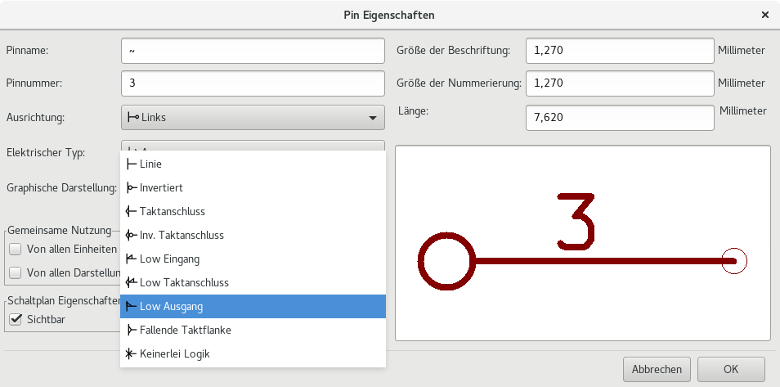
Typen von Elektrischen Anschlüssen
Den korrekten elektrischen Typ eines Anschlusses auszuwählen ist wichtig für das ERC-Werkzeug. Die elektrischen Typen sind definiert als:
-
Bidirektional: Gibt an, dass bidirektionale Anschlüsse zwischen Eingang und Ausgang umschaltbar sind (der Datenbus eines Mikroprozessors zum Beispiel).
-
Tri-State: Dies ist der übliche Tri-State Ausgang (mögliche Zustände: 0, 1 und hochohmig).
-
Passive is used for passive symbol pins, resistors, connectors, etc.
-
Nicht spezifiziert: Kann benutzt werden, wenn das Ergebnis des ERC egal ist.
-
Power input is used for the symbol’s power pins. Power pins are automatically connected to the other power input pins with the same name.
-
Spannungsausgang: Wird benutzt für Ausgänge von Spannungsreglern.
-
Offener Emitter und Offener Kollektor: Dieser Typ kann für Logik-Ausgänge verwendet werden, die solcherart gekennzeichnet sind.
-
Not connected is used when a symbol has a pin that has no internal connection.
Globale Anschlusseigenschaften
You can modify the length or text size of the name and/or number of all the pins using the Global command entry of the pin context menu. Click on the parameter you want to modify and type the new value which will then be applied to all of the current symbol’s pins.
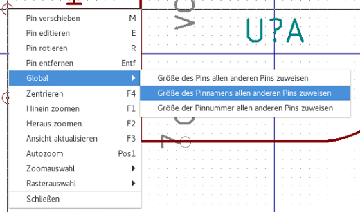
Anschlüsse für mehrere Einheiten und alternative Darstellung definieren
Symbols with multiple units and/or graphical representations are particularly problematic when creating and editing pins. The majority of pins are specific to each unit (because their pin number is specific to each unit) and to each symbolic representation (because their form and position is specific to each symbolic representation). The creation and the editing of pins can be problematic for symbols with multiple units per package and alternate symbolic representations. The symbol library editor allows the simultaneous creation of pins. By default, changes made to a pin are made for all units of a multiple unit symbol and both representations for symbols with an alternate symbolic representation.
Die einzige Ausnahme davon sind der Symboltyp und der Name des Anschlusses. Diese Abhängigkeit wurde eingeführt, um das Erstellen und Bearbeiten von Anschlüssen für die meisten Anwendungsfälle zu vereinfachen. Diese Abhängigkeit kann über ![]() in der Hauptwerkzeugleiste umgeschaltet werden. Das ermöglicht es Ihnen, Anschlüsse für jede Einheit und deren Darstellung komplett unabhängig zu erstellen.
in der Hauptwerkzeugleiste umgeschaltet werden. Das ermöglicht es Ihnen, Anschlüsse für jede Einheit und deren Darstellung komplett unabhängig zu erstellen.
A symbol can have two symbolic representations (representation known as``DeMorgan'') and can be made up of more than one unit as in the case of symbols with logic gates. For certain symbols, you may want several different graphic elements and pins. Like the relay sample shown in the previous section, a relay can be represented by three distinct units: a coil, switch contact 1, and switch contact 2.
The management of the symbols with multiple units and symbols with alternate symbolic representations is flexible. A pin can be common or specific to different units. A pin can also be common to both symbolic representations or specific to each symbolic representation.
Standardmäßig sind Anschlüsse spezifisch für jede Darstellungsform einer Einheit, da sich ihre Anschlussnummern für jede Einheit unterscheiden und ihr Symbol für jede Darstellungsform unterschiedlich ist. Wenn ein Pin für alle Einheiten gültig ist, muss er nur einmal gezeichnet werden, wie im Fall von Spannungsanschlüssen.
An example is the output pin 7400 quad dual input NAND gate. Since there are four units and two symbolic representations, there are eight separate output pins defined in the symbol definition. When creating a new 7400 symbol, unit A of the normal symbolic representation will be shown in the library editor. To edit the pin style in alternate symbolic representation, it must first be enabled by clicking the ![]() button on the tool bar. To edit the pin number for each unit, select the appropriate unit using the
button on the tool bar. To edit the pin number for each unit, select the appropriate unit using the  drop down control.
Symbol Fields
All library symbols are defined with four default fields. The reference designator, value, footprint assignment, and documentation file link fields are created whenever a symbol is created or copied. Only the reference designator and value fields are required. For existing fields, you can use the context menu commands by right-clicking on the pin. Symbols defined in libraries are typically defined with these four default fields. Additional fields such as vendor, part number, unit cost, etc. can be added to library symbols but generally this is done in the schematic editor so the additional fields can be applied to all of the symbols in the schematic.
Editing Symbol Fields
To edit an existing symbol field, right-click on the field text to show the field context menu shown below.
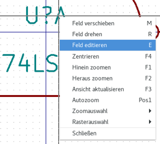
To edit undefined fields, add new fields, or delete optional fields ![]() on the main tool bar to open the field properties dialog shown below.
on the main tool bar to open the field properties dialog shown below.
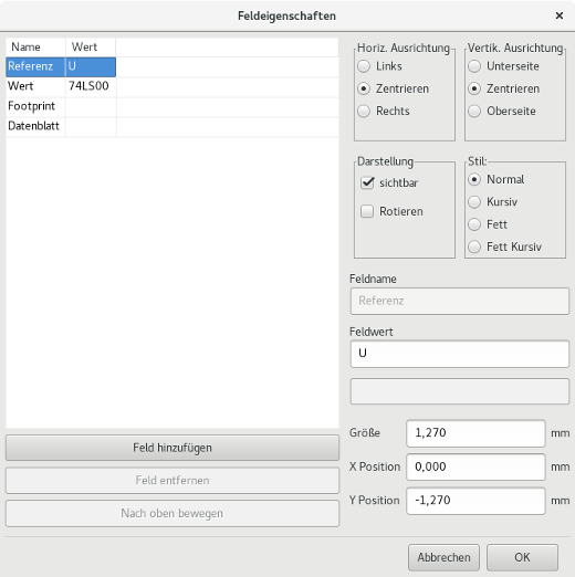
Fields are text sections associated with the symbol. Do not confuse them with the text belonging to the graphic representation of this symbol.
Wichtige Hinweise:
-
Modifying value fields effectively creates a new symbol using the current symbol as the starting point for the new symbol. This new symbol has the name contained in the value field when you save it to the currently selected library.
-
Der Dialog für die Feldeigenschaften wie oben zu sehen muss verwendet werden, um ein Feld zu bearbeiten das leer ist oder bei dem das "sichtbar" Attribut nicht gesetzt ist.
-
Der Footprint ist als absoluter Footprint im LIBNAME:FPNAME Format festgelegt, wobei LIBNAME der Name der Footprint Bibliothek ist, wie in der Footprintbibliothekstabelle hinterlegt (siehe Abschnitt "Footprint Bibliothek Tabellen" im Pcbnew "Referenz Handbuch") und FPNAME ist der Name des Footprints in der Bibliothek LIBNAME.
Spannungsversorgungssymbole
Power symbols are created the same way as normal symbols. It may be useful to place them in a dedicated library such as power.lib. Power symbols consist of a graphical symbol and a pin of the type "Power Invisible". Power port symbols are handled like any other symbol by the schematic capture software. Some precautions are essential. Below is an example of a power +5V symbol.
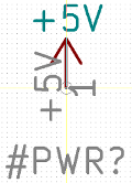
Um ein Spannungsversorgungssymbol zu erstellen führen Sie folgende Schritte aus:
-
Fügen Sie einen Anschluss des Typs "Spannungseingang" mit dem Namen +5V (wichtig, denn dieser Name wird die Verbindung zum Netz +5V herstellen), der Anschlussnummer 1 (die Nummer hat keine Bedeutung), einer Länge von 0 und dem "Symbol Typ" "Linie" hinzu.
-
Zeichnen Sie die Linien an den Anschluss wie gezeigt.
-
Der Anker des Symbols liegt auf dem Anschluss.
-
The symbol value is
+5V. -
The symbol reference is
#+5V. The reference text is not important except the first character which must be#to indicate that the symbol is a power symbol. By convention, every symbol in which the reference field starts with a#will not appear in the symbol list or in the netlist and the reference is declared as invisible.
Eine einfachere Methode ein Spannungsversorgungssymbol zu erstellen, ist es ein anderes Symbol als Vorlage zu verwenden:
-
Laden Sie ein bestehendes Spannungsversorgungssymbol.
-
Setzen Sie den Anschlussnamen auf den Namen des neuen Spannungsversorgungssymbols.
-
Setzen Sie das Feld Wert auf den gleichen Namen wie den Anschlussnamen, wenn Sie den Spannungsversorgungswert anzeigen wollen.
-
Save the new symbol.
LibEdit - Symbols
Überblick
A symbol consist of the following elements
-
Einer grafischen Repräsentation (geometrische Formen, Texte).
-
Anschlüssen (Pins).
-
Fields or associated text used by the post processors: netlist, symbols list.
Two fields are to be initialized: reference and value. The name of the design associated with the symbol, and the name of the associated footprint, the other fields are the free fields, they can generally remain empty, and could be filled during schematic capture.
However, managing the documentation associated with any symbol facilitates the research, use and maintenance of libraries. The associated documentation consists of
-
Einer Kommentarzeile.
-
Einer Zeile mit Schlüsselwörtern wie TTL CMOS NAND2, getrennt mit Leerzeichen.
-
Einem angehängten Dateinamen (zum Beispiel einem Anwendungshinweis oder eine PDF Datei).
Das Standardverzeichnis für angehängte Dateien:
kicad/share/library/doc
Wenn dieses nicht gefunden wird:
kicad/library/doc
Unter Linux:
/usr/local/kicad/share/library/doc
/usr/share/kicad/library/doc
/usr/local/share/kicad/library/doc
Key words allow you to selectively search for a symbol according to various selection criteria. Comments and key words are displayed in various menus, and particularly when you select a symbol from the library.
The symbol also has an anchoring point. A rotation or a mirror is made relative to this anchor point and during a placement this point is used as a reference position. It is thus useful to position this anchor accurately.
A symbol can have aliases, i.e. equivalent names. This allows you to considerably reduce the number of symbols that need to be created (for example, a 74LS00 can have aliases such as 74000, 74HC00, 74HCT00…).
Finally, the symbols are distributed in libraries (classified by topics, or manufacturer) in order to facilitate their management.
Position a symbol anchor
Der Anker befindet sich an den Koordinaten (0,0) und wird durch die blauen Achsen auf Ihrem Bildschirm dargestellt.
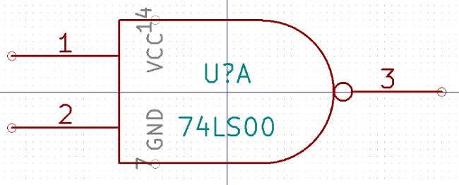
Der Anker kann neu gesetzt werden, indem Sie das Symbol ![]() auswählen und auf die neue gewünschte Ankerposition klicken. Die Zeichnung wird automatisch auf den neuen Ankerpunkt zentriert.
auswählen und auf die neue gewünschte Ankerposition klicken. Die Zeichnung wird automatisch auf den neuen Ankerpunkt zentriert.
Symbol aliases
An alias is another name corresponding to the same symbol in the library. Symbols with similar pin-out and representation can then be represented by only one symbol, having several aliases (e.g. 7400 with alias 74LS00, 74HC00, 74LS37 ).
Die Benutzung von Aliasen erlaubt es Ihnen vollständige Bibliotheken schnell zu erstellen. Und zusätzlich dazu, dass diese Bibliotheken deutlich kompakter sind, werden diese schneller von KiCad geladen.
Um die Liste der Aliase zu bearbeiten, müssen Sie das Hauptbearbeitungsfenster über das Symbol ![]() auswählen und den Ordner der Aliase auswählen.
auswählen und den Ordner der Aliase auswählen.
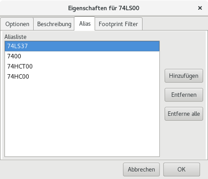
Jetzt können Sie den gewünschten Alias ergänzen oder entfernen. Der aktuelle Alias kann selbstverständlich nicht entfernt werden da er gerade bearbeitet wird.
To remove all aliases, you have firstly to select the root symbol. The first symbol in the alias list in the window of selection of the main toolbar.
Symbol fields
The field editor is called via the icon ![]() .
.
There are four special fields (texts attached to the symbol), and configurable user fields

Spezialfelder:
-
Referenz.
-
Value. It is the symbol name in the library and the default value field in schematic.
-
Footprint. Das ist der Name des Footprints der für die Leiterplatte verwendet wird. Nicht sonderlich hilfreich wenn CvPcb genutzt wird, um die Footprint Liste zu erzeugen, aber zwingend erforderlich wenn CvPcb nicht benutzt wird.
-
Datenblatt. Das ist ein reserviertes Feld, derzeit nicht genutzt.
Symbol documentation
To edit documentation information, it is necessary to call the main editing window of the symbol via the icon ![]() and to select the document folder.
and to select the document folder.
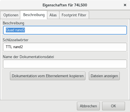
Be sure to select the right alias, or the root symbol, because this documentation is the only characteristic which differs between aliases. The "Copy Doc" button allows you to copy the documentation information from the root symbol towards the currently edited alias.
Symbol keywords
Keywords allow you to search in a selective way for a symbol according to specific selection criteria (function, technological family, etc.)
Das Eeschema Suchwerkzeug unterscheidet nicht nach Groß-/Kleinschreibung. Die aktuell in den Bibliotheken verwendeten Schlüsselwörter sind:
-
CMOS TTL für Logik-Familien
-
AND2 NOR3 XOR2 INV… für die Gatter (AND2 = UND Gatter mit 2 Eingängen, NOR3 = NOR Gatter mit 3 Eingängen).
-
JKFF DFF… für JK- oder D- Flip-Flop.
-
ADC, DAC, MUX… für Analog-Digital Wandler, Digital-Analog Wandler, Multiplexer
-
OpenCol for the gates with open collector output. Thus if in the schematic capture software, you search the symbol: by keywords NAND2 OpenCol Eeschema will display the list of symbols having these 2 key words.
Symbol documentation (Doc)
The line of comment (and keywords) is displayed in various menus, particularly when you select a symbol in the displayed symbols list of a library and in the ViewLib menu.
If this Doc. file exists, it is also accessible in the schematic capture software, in the pop-up menu displayed by right-clicking on the symbol.
Zugehörige Dokumentationsdatei
Zeigt an, dass eine angehängte Datei (Dokumentation, Anwendungsschaltplan) verfügbar ist (PDF-Datei, Schaltplan Diagramm, usw.).
Footprintfilter für CvPcb
You can enter a list of allowed footprints for the symbol. This list acts as a filter used by CvPcb to display only the allowed footprints. A void list does not filter anything.
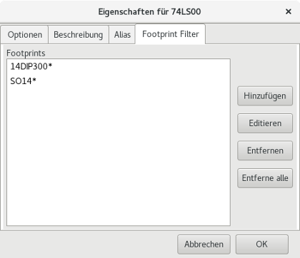
Platzhalter Zeichen sind zulässig.
SO14* erlaubt CvPcb alle Footprints anzuzeigen, deren Name mit SO14 anfängt.
Für einen Widerstand zeigt R? alle Footprints mit insgesamt zwei Zeichen im Namen an, wobei aber nur Namen gezeigt werden die mit R beginnen.
Hier sind Beispiele mit und ohne Filterung.
Mit Filterung:
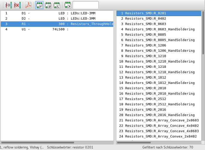
Ohne Filterung:
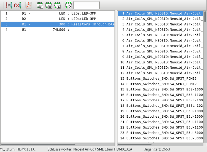
Symbolbibliothek
You can easily compile a graphic symbols library file containing frequently used symbols. This can be used for the creation of symbols (triangles, the shape of AND, OR, Exclusive OR gates, etc.) for saving and subsequent re-use.
These files are stored by default in the library directory and have a '.sym' extension. These symbols are not gathered in libraries like the normal symbols because they are generally not so many.
Ein Symbol erstellen oder exportieren
A symbol can be exported with the button ![]() . You can generally create only one graphic, also it will be a good idea to delete all pins, if they exist.
. You can generally create only one graphic, also it will be a good idea to delete all pins, if they exist.
Ein Symbol importieren
Importing allows you to add graphics to a symbol you are editing. A symbol is imported with the button ![]() . Imported graphics are added as they were created in existing graphics.
. Imported graphics are added as they were created in existing graphics.
Symbol Library Browser
Einleitung
The Symbol Library Browser allows you to quickly examine the content of symbol libraries. The Symbol Library Viewer can be accessed by clicking ![]() icon on the main toolbar, selecting "Library Browser" entry in the "View" menu or double clicking symbol image on "Choose Symbol" window.
icon on the main toolbar, selecting "Library Browser" entry in the "View" menu or double clicking symbol image on "Choose Symbol" window.
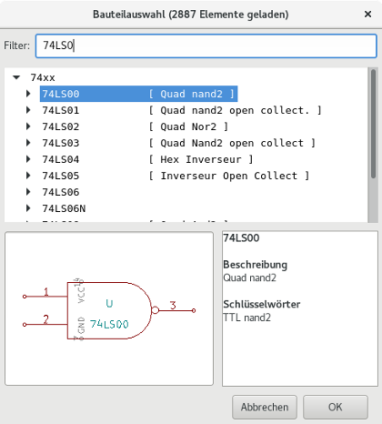
Bibliotheksbrowser - Hauptfenster
To examine the contents of a library, select a library from the list on the left hand pane. All symbols in the selected library will appear in the second pane. Select a symbol name to view the symbol.
Symbol Library Browser Top Toolbar
The top tool bar in Symbol Library Brower is shown below.

Die möglichen Befehle sind:
|
Selection of the desired library which can be also selected in the displayed list. |
|
Selection of the symbol which can be also selected in the displayed list. |
|
Display previous symbol. |
|
Display next symbol. |
|
Zoom tools. |
|
Selection of the representation (normal or converted) if exist. |
|
Selection of the unit for symbols that contain multiple units. |
|
If it exist, display the associated documents. Exists only when called by the place symbol dialog frame from Eeschema. |
|
Close the browser and place the selected symbol in Eeschema. This icon is only displayed when browser has been called from Eeschema (double click on a symbol in the component chooser). |
Erstellen angepasster Dateien für Netzlisten und Stücklisten
Zwischenzeitliche Netzlistendatei
Stücklistendateien (BOM-Dateien) und Netzlistendateien können aus einer zwischenzeitlichen Netzlistendatei, die von Eeschema erzeugt wird, erstellt werden.
Diese Datei benutzt XML Syntax und wird "zwischenzeitliche Netzliste" genannt. Die Zwischennetzliste enthält eine große Menge von Daten über Ihre Leiterplatte und aufgrund dessen kann sie dafür genutzt werden, eine Stückliste und andere Berichte zu erstellen.
Abhängig von der Ausgabe (Stückliste oder Netzliste) werden unterschiedliche Untermengen der kompletten Zwischennetzlistendatei für die Nachbearbeitung verwendet.
Schaltplanbeispiel
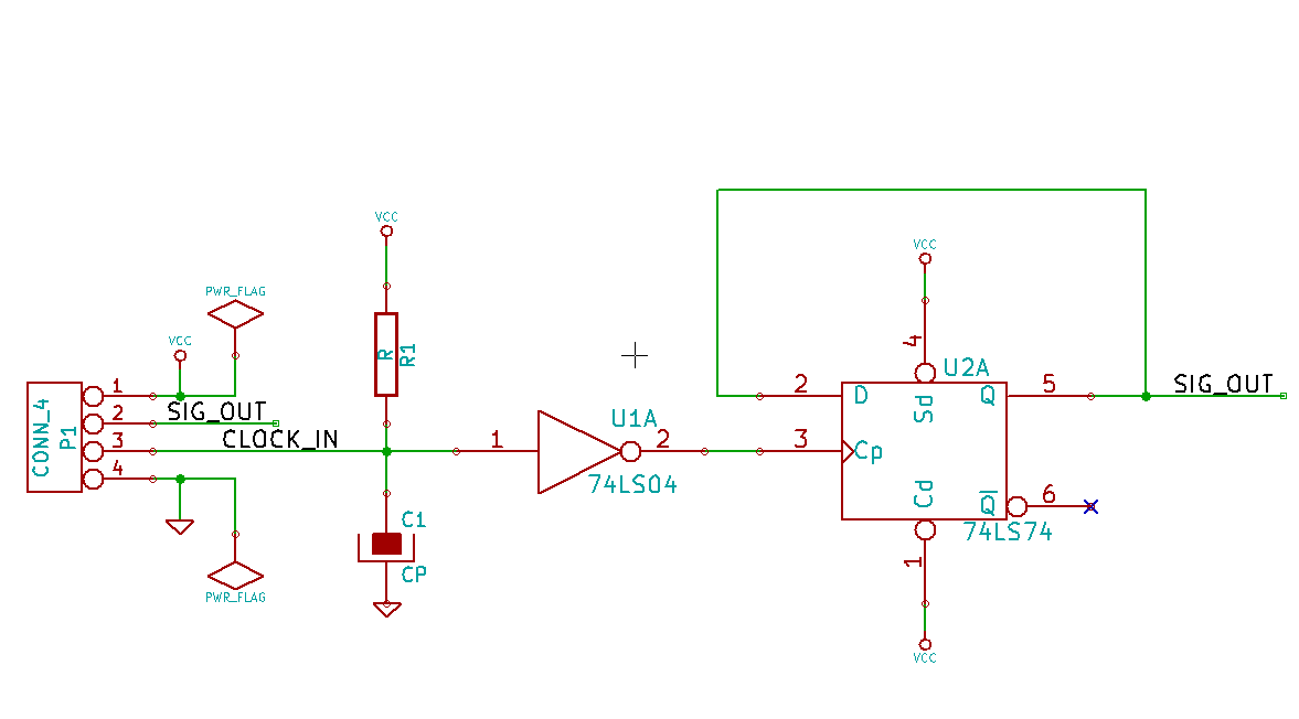
Dateibeispiel der Zwischennetzliste
Die korrespondierende Zwischennetzliste (als XML-Datei) des Schaltkreises ist unten zu sehen.
<?xml version="1.0" encoding="utf-8"?>
<export version="D">
<design>
<source>F:\kicad_aux\netlist_test\netlist_test.sch</source>
<date>29/08/2010 20:35:21</date>
<tool>eeschema (2010-08-28 BZR 2458)-unstable</tool>
</design>
<components>
<comp ref="P1">
<value>CONN_4</value>
<libsource lib="conn" part="CONN_4"/>
<sheetpath names="/" tstamps="/"/>
<tstamp>4C6E2141</tstamp>
</comp>
<comp ref="U2">
<value>74LS74</value>
<libsource lib="74xx" part="74LS74"/>
<sheetpath names="/" tstamps="/"/>
<tstamp>4C6E20BA</tstamp>
</comp>
<comp ref="U1">
<value>74LS04</value>
<libsource lib="74xx" part="74LS04"/>
<sheetpath names="/" tstamps="/"/>
<tstamp>4C6E20A6</tstamp>
</comp>
<comp ref="C1">
<value>CP</value>
<libsource lib="device" part="CP"/>
<sheetpath names="/" tstamps="/"/>
<tstamp>4C6E2094</tstamp>
</comp>
<comp ref="R1">
<value>R</value>
<libsource lib="device" part="R"/>
<sheetpath names="/" tstamps="/"/>
<tstamp>4C6E208A</tstamp>
</comp>
</components>
<libparts>
<libpart lib="device" part="C">
<description>Condensateur non polarise</description>
<footprints>
<fp>SM*</fp>
<fp>C?</fp>
<fp>C1-1</fp>
</footprints>
<fields>
<field name="Reference">C</field>
<field name="Value">C</field>
</fields>
<pins>
<pin num="1" name="~" type="passive"/>
<pin num="2" name="~" type="passive"/>
</pins>
</libpart>
<libpart lib="device" part="R">
<description>Resistance</description>
<footprints>
<fp>R?</fp>
<fp>SM0603</fp>
<fp>SM0805</fp>
<fp>R?-*</fp>
<fp>SM1206</fp>
</footprints>
<fields>
<field name="Reference">R</field>
<field name="Value">R</field>
</fields>
<pins>
<pin num="1" name="~" type="passive"/>
<pin num="2" name="~" type="passive"/>
</pins>
</libpart>
<libpart lib="conn" part="CONN_4">
<description>Symbole general de connecteur</description>
<fields>
<field name="Reference">P</field>
<field name="Value">CONN_4</field>
</fields>
<pins>
<pin num="1" name="P1" type="passive"/>
<pin num="2" name="P2" type="passive"/>
<pin num="3" name="P3" type="passive"/>
<pin num="4" name="P4" type="passive"/>
</pins>
</libpart>
<libpart lib="74xx" part="74LS04">
<description>Hex Inverseur</description>
<fields>
<field name="Reference">U</field>
<field name="Value">74LS04</field>
</fields>
<pins>
<pin num="1" name="~" type="input"/>
<pin num="2" name="~" type="output"/>
<pin num="3" name="~" type="input"/>
<pin num="4" name="~" type="output"/>
<pin num="5" name="~" type="input"/>
<pin num="6" name="~" type="output"/>
<pin num="7" name="GND" type="power_in"/>
<pin num="8" name="~" type="output"/>
<pin num="9" name="~" type="input"/>
<pin num="10" name="~" type="output"/>
<pin num="11" name="~" type="input"/>
<pin num="12" name="~" type="output"/>
<pin num="13" name="~" type="input"/>
<pin num="14" name="VCC" type="power_in"/>
</pins>
</libpart>
<libpart lib="74xx" part="74LS74">
<description>Dual D FlipFlop, Set & Reset</description>
<docs>74xx/74hc_hct74.pdf</docs>
<fields>
<field name="Reference">U</field>
<field name="Value">74LS74</field>
</fields>
<pins>
<pin num="1" name="Cd" type="input"/>
<pin num="2" name="D" type="input"/>
<pin num="3" name="Cp" type="input"/>
<pin num="4" name="Sd" type="input"/>
<pin num="5" name="Q" type="output"/>
<pin num="6" name="~Q" type="output"/>
<pin num="7" name="GND" type="power_in"/>
<pin num="8" name="~Q" type="output"/>
<pin num="9" name="Q" type="output"/>
<pin num="10" name="Sd" type="input"/>
<pin num="11" name="Cp" type="input"/>
<pin num="12" name="D" type="input"/>
<pin num="13" name="Cd" type="input"/>
<pin num="14" name="VCC" type="power_in"/>
</pins>
</libpart>
</libparts>
<libraries>
<library logical="device">
<uri>F:\kicad\share\library\device.lib</uri>
</library>
<library logical="conn">
<uri>F:\kicad\share\library\conn.lib</uri>
</library>
<library logical="74xx">
<uri>F:\kicad\share\library\74xx.lib</uri>
</library>
</libraries>
<nets>
<net code="1" name="GND">
<node ref="U1" pin="7"/>
<node ref="C1" pin="2"/>
<node ref="U2" pin="7"/>
<node ref="P1" pin="4"/>
</net>
<net code="2" name="VCC">
<node ref="R1" pin="1"/>
<node ref="U1" pin="14"/>
<node ref="U2" pin="4"/>
<node ref="U2" pin="1"/>
<node ref="U2" pin="14"/>
<node ref="P1" pin="1"/>
</net>
<net code="3" name="">
<node ref="U2" pin="6"/>
</net>
<net code="4" name="">
<node ref="U1" pin="2"/>
<node ref="U2" pin="3"/>
</net>
<net code="5" name="/SIG_OUT">
<node ref="P1" pin="2"/>
<node ref="U2" pin="5"/>
<node ref="U2" pin="2"/>
</net>
<net code="6" name="/CLOCK_IN">
<node ref="R1" pin="2"/>
<node ref="C1" pin="1"/>
<node ref="U1" pin="1"/>
<node ref="P1" pin="3"/>
</net>
</nets>
</export>
Umwandlung in ein neues Netzlistenformat
Unter Anwendung eines Nachtbearbeitungsfilters auf die Zwischennetzlistendatei können Sie fremde Netzlistenformate und auch Stücklisten erzeugen. Weil diese Umwandlung eine Text zu Text Umwandlung ist, kann dieser Nachtbearbeitungsfilter in Python, XSLT oder jedem anderen Werkzeug geschrieben werden, das XML als Eingabe verarbeiten kann.
XSLT selbst ist eine XML-Sprache die sehr gut für XML Umwandlungen geeignet ist. Es gibt ein freies Programm mit dem Namen xsltproc, das Sie selbst herunterladen und installieren können. Das Programm xsltproc kann verwendet werden um die Zwischennetzliste zu lesen, eine Stylesheet Umwandlung durchzuführen und das Ergebnis in einer Ausgabedatei zu speichern. Die Benutzung von xsltproc erfordert eine Stylesheetdatei die den XSLT-Konventionen folgt. Der komplette Umwandlungsprozess wird von Eeschema durchgeführt, wenn es einmal eingerichtet wurde xsltproc in einer bestimmten Weise aufzurufen.
XSLT-Vorgehensweise
Das Dokument, das die XSL-Umwandlung (XSLT) beschreibt, gibt es unter:
Erstellen einer PadsPcb Netzlistendatei
Das PadsPcb Format besteht aus zwei Teilen.
-
Die Footprintliste.
-
Die Netzeliste: Gruppiert Referenzen der Pads nach Netzen.
Direkt unten ist ein Stylesheet welches die Zwischennetzlistendatei in ein PadsPcb Netzlistenformat umwandelt:
<?xml version="1.0" encoding="ISO-8859-1"?>
<!--XSL style sheet to Eeschema Generic Netlist Format to PADS netlist format
Copyright (C) 2010, SoftPLC Corporation.
GPL v2.
How to use:
https://lists.launchpad.net/kicad-developers/msg05157.html
-->
<!DOCTYPE xsl:stylesheet [
<!ENTITY nl "
"> <!--new line CR, LF -->
]>
<xsl:stylesheet version="1.0" xmlns:xsl="http://www.w3.org/1999/XSL/Transform">
<xsl:output method="text" omit-xml-declaration="yes" indent="no"/>
<xsl:template match="/export">
<xsl:text>*PADS-PCB*&nl;*PART*&nl;</xsl:text>
<xsl:apply-templates select="components/comp"/>
<xsl:text>&nl;*NET*&nl;</xsl:text>
<xsl:apply-templates select="nets/net"/>
<xsl:text>*END*&nl;</xsl:text>
</xsl:template>
<!-- for each component -->
<xsl:template match="comp">
<xsl:text> </xsl:text>
<xsl:value-of select="@ref"/>
<xsl:text> </xsl:text>
<xsl:choose>
<xsl:when test = "footprint != '' ">
<xsl:apply-templates select="footprint"/>
</xsl:when>
<xsl:otherwise>
<xsl:text>unknown</xsl:text>
</xsl:otherwise>
</xsl:choose>
<xsl:text>&nl;</xsl:text>
</xsl:template>
<!-- for each net -->
<xsl:template match="net">
<!-- nets are output only if there is more than one pin in net -->
<xsl:if test="count(node)>1">
<xsl:text>*SIGNAL* </xsl:text>
<xsl:choose>
<xsl:when test = "@name != '' ">
<xsl:value-of select="@name"/>
</xsl:when>
<xsl:otherwise>
<xsl:text>N-</xsl:text>
<xsl:value-of select="@code"/>
</xsl:otherwise>
</xsl:choose>
<xsl:text>&nl;</xsl:text>
<xsl:apply-templates select="node"/>
</xsl:if>
</xsl:template>
<!-- for each node -->
<xsl:template match="node">
<xsl:text> </xsl:text>
<xsl:value-of select="@ref"/>
<xsl:text>.</xsl:text>
<xsl:value-of select="@pin"/>
<xsl:text>&nl;</xsl:text>
</xsl:template>
</xsl:stylesheet>
Und dies ist die PadsPcb Ausgabe nach dem Durchlauf von xsltproc:
*PADS-PCB*
*PART*
P1 unknown
U2 unknown
U1 unknown
C1 unknown
R1 unknown
*NET*
*SIGNAL* GND
U1.7
C1.2
U2.7
P1.4
*SIGNAL* VCC
R1.1
U1.14
U2.4
U2.1
U2.14
P1.1
*SIGNAL* N-4
U1.2
U2.3
*SIGNAL* /SIG_OUT
P1.2
U2.5
U2.2
*SIGNAL* /CLOCK_IN
R1.2
C1.1
U1.1
P1.3

*END*
Die Befehlszeile um diese Umwandlung durchzuführen lautet:
kicad\\bin\\xsltproc.exe -o test.net kicad\\bin\\plugins\\netlist_form_pads-pcb.xsl test.tmp
Eine Cadstar Netzlistendatei erstellen
Das Cadstarformat besteht aus zwei Teilen.
-
Die Footprintliste.
-
Die Netzeliste: Gruppiert Referenzen der Pads nach Netzen.
Hier ist die Stylesheet-Datei um diese spezielle Umwandlung durchzuführen.
<?xml version="1.0" encoding="ISO-8859-1"?>
<!--XSL style sheet to Eeschema Generic Netlist Format to CADSTAR netlist format
Copyright (C) 2010, Jean-Pierre Charras.
Copyright (C) 2010, SoftPLC Corporation.
GPL v2.
<!DOCTYPE xsl:stylesheet [
<!ENTITY nl "
"> <!--new line CR, LF -->
]>
<xsl:stylesheet version="1.0" xmlns:xsl="http://www.w3.org/1999/XSL/Transform">
<xsl:output method="text" omit-xml-declaration="yes" indent="no"/>
<!-- Netlist header -->
<xsl:template match="/export">
<xsl:text>.HEA&nl;</xsl:text>
<xsl:apply-templates select="design/date"/> <!-- Generate line .TIM <time> -->
<xsl:apply-templates select="design/tool"/> <!-- Generate line .APP <eeschema version> -->
<xsl:apply-templates select="components/comp"/> <!-- Generate list of components -->
<xsl:text>&nl;&nl;</xsl:text>
<xsl:apply-templates select="nets/net"/> <!-- Generate list of nets and connections -->
<xsl:text>&nl;.END&nl;</xsl:text>
</xsl:template>
<!-- Generate line .TIM 20/08/2010 10:45:33 -->
<xsl:template match="tool">
<xsl:text>.APP "</xsl:text>
<xsl:apply-templates/>
<xsl:text>"&nl;</xsl:text>
</xsl:template>
<!-- Generate line .APP "eeschema (2010-08-17 BZR 2450)-unstable" -->
<xsl:template match="date">
<xsl:text>.TIM </xsl:text>
<xsl:apply-templates/>
<xsl:text>&nl;</xsl:text>
</xsl:template>
<!-- for each component -->
<xsl:template match="comp">
<xsl:text>.ADD_COM </xsl:text>
<xsl:value-of select="@ref"/>
<xsl:text> </xsl:text>
<xsl:choose>
<xsl:when test = "value != '' ">
<xsl:text>"</xsl:text> <xsl:apply-templates select="value"/> <xsl:text>"</xsl:text>
</xsl:when>
<xsl:otherwise>
<xsl:text>""</xsl:text>
</xsl:otherwise>
</xsl:choose>
<xsl:text>&nl;</xsl:text>
</xsl:template>
<!-- for each net -->
<xsl:template match="net">
<!-- nets are output only if there is more than one pin in net -->
<xsl:if test="count(node)>1">
<xsl:variable name="netname">
<xsl:text>"</xsl:text>
<xsl:choose>
<xsl:when test = "@name != '' ">
<xsl:value-of select="@name"/>
</xsl:when>
<xsl:otherwise>
<xsl:text>N-</xsl:text>
<xsl:value-of select="@code"/>
</xsl:otherwise>
</xsl:choose>
<xsl:text>"&nl;</xsl:text>
</xsl:variable>
<xsl:apply-templates select="node" mode="first"/>
<xsl:value-of select="$netname"/>
<xsl:apply-templates select="node" mode="others"/>
</xsl:if>
</xsl:template>
<!-- for each node -->
<xsl:template match="node" mode="first">
<xsl:if test="position()=1">
<xsl:text>.ADD_TER </xsl:text>
<xsl:value-of select="@ref"/>
<xsl:text>.</xsl:text>
<xsl:value-of select="@pin"/>
<xsl:text> </xsl:text>
</xsl:if>
</xsl:template>
<xsl:template match="node" mode="others">
<xsl:choose>
<xsl:when test='position()=1'>
</xsl:when>
<xsl:when test='position()=2'>
<xsl:text>.TER </xsl:text>
</xsl:when>
<xsl:otherwise>
<xsl:text> </xsl:text>
</xsl:otherwise>
</xsl:choose>
<xsl:if test="position()>1">
<xsl:value-of select="@ref"/>
<xsl:text>.</xsl:text>
<xsl:value-of select="@pin"/>
<xsl:text>&nl;</xsl:text>
</xsl:if>
</xsl:template>
</xsl:stylesheet>
Hier ist die Cadstar Ausgabedatei.
.HEA
.TIM 21/08/2010 08:12:08
.APP "eeschema (2010-08-09 BZR 2439)-unstable"
.ADD_COM P1 "CONN_4"
.ADD_COM U2 "74LS74"
.ADD_COM U1 "74LS04"
.ADD_COM C1 "CP"
.ADD_COM R1 "R"


.ADD_TER U1.7 "GND"
.TER     C1.2
         U2.7
         P1.4
.ADD_TER R1.1 "VCC"
.TER     U1.14
         U2.4
         U2.1
         U2.14
         P1.1
.ADD_TER U1.2 "N-4"
.TER     U2.3
.ADD_TER P1.2 "/SIG_OUT"
.TER     U2.5
         U2.2
.ADD_TER R1.2 "/CLOCK_IN"
.TER     C1.1
         U1.1
         P1.3

.END
Eine OrcadPCB2 Netzlistendatei erstellen
Dieses Format hat nur einen Teil, die Footprintliste. Jeder Footprint enthält selbst seine Liste von Pads mit einer Referenz zu einem Netz.
Hier ist das Stylesheet für diese spezielle Umwandlung:
<?xml version="1.0" encoding="ISO-8859-1"?>
<!--XSL style sheet to Eeschema Generic Netlist Format to CADSTAR netlist format
Copyright (C) 2010, SoftPLC Corporation.
GPL v2.
How to use:
https://lists.launchpad.net/kicad-developers/msg05157.html
-->
<!DOCTYPE xsl:stylesheet [
<!ENTITY nl "
"> <!--new line CR, LF -->
]>
<xsl:stylesheet version="1.0" xmlns:xsl="http://www.w3.org/1999/XSL/Transform">
<xsl:output method="text" omit-xml-declaration="yes" indent="no"/>
<!--
Netlist header
Creates the entire netlist
(can be seen as equivalent to main function in C
-->
<xsl:template match="/export">
<xsl:text>( { Eeschema Netlist Version 1.1 </xsl:text>
<!-- Generate line .TIM <time> -->
<xsl:apply-templates select="design/date"/>
<!-- Generate line eeschema version ... -->
<xsl:apply-templates select="design/tool"/>
<xsl:text>}&nl;</xsl:text>
<!-- Generate the list of components -->
<xsl:apply-templates select="components/comp"/> <!-- Generate list of components -->
<!-- end of file -->
<xsl:text>)&nl;*&nl;</xsl:text>
</xsl:template>
<!--
Generate id in header like "eeschema (2010-08-17 BZR 2450)-unstable"
-->
<xsl:template match="tool">
<xsl:apply-templates/>
</xsl:template>
<!--
Generate date in header like "20/08/2010 10:45:33"
-->
<xsl:template match="date">
<xsl:apply-templates/>
<xsl:text>&nl;</xsl:text>
</xsl:template>
<!--
This template read each component
(path = /export/components/comp)
creates lines:
( 3EBF7DBD $noname U1 74LS125
... pin list ...
)
and calls "create_pin_list" template to build the pin list
-->
<xsl:template match="comp">
<xsl:text> ( </xsl:text>
<xsl:choose>
<xsl:when test = "tstamp != '' ">
<xsl:apply-templates select="tstamp"/>
</xsl:when>
<xsl:otherwise>
<xsl:text>00000000</xsl:text>
</xsl:otherwise>
</xsl:choose>
<xsl:text> </xsl:text>
<xsl:choose>
<xsl:when test = "footprint != '' ">
<xsl:apply-templates select="footprint"/>
</xsl:when>
<xsl:otherwise>
<xsl:text>$noname</xsl:text>
</xsl:otherwise>
</xsl:choose>
<xsl:text> </xsl:text>
<xsl:value-of select="@ref"/>
<xsl:text> </xsl:text>
<xsl:choose>
<xsl:when test = "value != '' ">
<xsl:apply-templates select="value"/>
</xsl:when>
<xsl:otherwise>
<xsl:text>"~"</xsl:text>
</xsl:otherwise>
</xsl:choose>
<xsl:text>&nl;</xsl:text>
<xsl:call-template name="Search_pin_list" >
<xsl:with-param name="cmplib_id" select="libsource/@part"/>
<xsl:with-param name="cmp_ref" select="@ref"/>
</xsl:call-template>
<xsl:text> )&nl;</xsl:text>
</xsl:template>
<!--
This template search for a given lib component description in list
lib component descriptions are in /export/libparts,
and each description start at ./libpart
We search here for the list of pins of the given component
This template has 2 parameters:
"cmplib_id" (reference in libparts)
"cmp_ref" (schematic reference of the given component)
-->
<xsl:template name="Search_pin_list" >
<xsl:param name="cmplib_id" select="0" />
<xsl:param name="cmp_ref" select="0" />
<xsl:for-each select="/export/libparts/libpart">
<xsl:if test = "@part = $cmplib_id ">
<xsl:apply-templates name="build_pin_list" select="pins/pin">
<xsl:with-param name="cmp_ref" select="$cmp_ref"/>
</xsl:apply-templates>
</xsl:if>
</xsl:for-each>
</xsl:template>
<!--
This template writes the pin list of a component
from the pin list of the library description
The pin list from library description is something like
<pins>
<pin num="1" type="passive"/>
<pin num="2" type="passive"/>
</pins>
Output pin list is ( <pin num> <net name> )
something like
( 1 VCC )
( 2 GND )
-->
<xsl:template name="build_pin_list" match="pin">
<xsl:param name="cmp_ref" select="0" />
<!-- write pin numner and separator -->
<xsl:text> ( </xsl:text>
<xsl:value-of select="@num"/>
<xsl:text> </xsl:text>
<!-- search net name in nets section and write it: -->
<xsl:variable name="pinNum" select="@num" />
<xsl:for-each select="/export/nets/net">
<!-- net name is output only if there is more than one pin in net
else use "?" as net name, so count items in this net
-->
<xsl:variable name="pinCnt" select="count(node)" />
<xsl:apply-templates name="Search_pin_netname" select="node">
<xsl:with-param name="cmp_ref" select="$cmp_ref"/>
<xsl:with-param name="pin_cnt_in_net" select="$pinCnt"/>
<xsl:with-param name="pin_num"> <xsl:value-of select="$pinNum"/>
</xsl:with-param>
</xsl:apply-templates>
</xsl:for-each>
<!-- close line -->
<xsl:text> )&nl;</xsl:text>
</xsl:template>
<!--
This template writes the pin netname of a given pin of a given component
from the nets list
The nets list description is something like
<nets>
<net code="1" name="GND">
<node ref="J1" pin="20"/>
<node ref="C2" pin="2"/>
</net>
<net code="2" name="">
<node ref="U2" pin="11"/>
</net>
</nets>
This template has 2 parameters:
"cmp_ref" (schematic reference of the given component)
"pin_num" (pin number)
-->
<xsl:template name="Search_pin_netname" match="node">
<xsl:param name="cmp_ref" select="0" />
<xsl:param name="pin_num" select="0" />
<xsl:param name="pin_cnt_in_net" select="0" />
<xsl:if test = "@ref = $cmp_ref ">
<xsl:if test = "@pin = $pin_num">
<!-- net name is output only if there is more than one pin in net
else use "?" as net name
-->
<xsl:if test = "$pin_cnt_in_net>1">
<xsl:choose>
<!-- if a net has a name, use it,
else build a name from its net code
-->
<xsl:when test = "../@name != '' ">
<xsl:value-of select="../@name"/>
</xsl:when>
<xsl:otherwise>
<xsl:text>$N-0</xsl:text><xsl:value-of select="../@code"/>
</xsl:otherwise>
</xsl:choose>
</xsl:if>
<xsl:if test = "$pin_cnt_in_net <2">
<xsl:text>?</xsl:text>
</xsl:if>
</xsl:if>
</xsl:if>
</xsl:template>
</xsl:stylesheet>
Hier ist die OrcadPCB2 Ausgabedatei.
( { Eeschema Netlist Version 1.1  29/08/2010 21:07:51
eeschema (2010-08-28 BZR 2458)-unstable}
 ( 4C6E2141 $noname P1 CONN_4
  (  1 VCC )
  (  2 /SIG_OUT )
  (  3 /CLOCK_IN )
  (  4 GND )
 )
 ( 4C6E20BA $noname U2 74LS74
  (  1 VCC )
  (  2 /SIG_OUT )
  (  3 N-04 )
  (  4 VCC )
  (  5 /SIG_OUT )
  (  6 ? )
  (  7 GND )
  (  14 VCC )
 )
 ( 4C6E20A6 $noname U1 74LS04
  (  1 /CLOCK_IN )
  (  2 N-04 )
  (  7 GND )
  (  14 VCC )
 )
 ( 4C6E2094 $noname C1 CP
  (  1 /CLOCK_IN )
  (  2 GND )
 )
 ( 4C6E208A $noname R1 R
  (  1 VCC )
  (  2 /CLOCK_IN )
 )
)
*
Eeschema Plugin-Schnittstelle
Zwischenzeitliche Netzlistenkonverter können automatisch aus Eeschema gestartet werden.
Das Dialogfenster aufrufen
Sie können ein neues Netzlisten-Plugin hinzufügen mit einem Klick auf "Plugin hinzufügen".

So sehen die Konfigurationsdaten für das PadsPcb Plugin aus:

Konfiguration der Plugin-Parameter
Folgende Informationen werden in der Eeschema Plug-In Konfiguration benötigt:
-
Titel: Zum Beispiel der Name des Netzlistenformats.
-
Netzliste Befehl: Der Audruf um den Konverter zu starten.
Sobald Sie auf den Button Erstellen drücken, wird folgendes passieren:
-
Eeschema erzeugt eine zwischenzeitliche Netzlistendatei im XML-Format, zum Beispiel test.xml.
-
Eeschema startet das Plugin und liest test.xml ein und erzeugt test.net.
Netzlistendateien über die Befehlszeile erzeugen
Angenommen wir benutzen das Programm xsltproc.exe um ein Stylesheet auf die zwischenzeitliche Netzlistendatei anzuwenden, dann wird xsltproc.exe mit folgendem Befehl ausgeführt:
xsltproc.exe -o <output filename> < style-sheet filename> <input XML file to convert>
In KiCad unter Windows ist die Befehlszeile wie folgt:
f:/kicad/bin/xsltproc.exe -o "%O" f:/kicad/bin/plugins/netlist_form_pads-pcb.xsl "%I"
Unter Linux sieht der Befehl (abhängig vom Installationsort) wie folgt aus:
xsltproc -o "%O" /usr/local/kicad/bin/plugins/netlist_form_pads-pcb.xsl "%I"
Wobei netliste_form_pads-pcb.xsl das Stylesheet ist, das Sie anwenden. Vergessen Sie nicht die Anführungsstriche um die Dateinamen, dies erlaubt es Leerzeichen zu verwenden nach der Ersetzung durch Eeschema.
Das Befehlszeilenformat akzeptiert Parameter für Dateinamen:
Die unterstützten Formatierungsparameter sind:
-
%B ⇒ Basisdateiname und Pfad der ausgewählten Ausgabedatei ohne Pfad und Erweiterung.
-
%I ⇒ Kompletter Dateiname und Pfad der temporären Eingangsdatei (die Zwischennetzliste).
-
%O ⇒ Kompletter Dateiname und Pfad der vom Benutzer gewählten Ausgabedatei.
%I wird vom tatsächlichen Zwischendateiname ersetzt.
%O wird vom tatsächlichen Ausgabedateiname ersetzt.
Befehlszeilenformat: Beispiel für xsltproc
Das Befehlszeilenformat für xsltproc sieht wie folgt aus:
<Pfad zu xsltproc>xsltproc <xsltproc Parameter>
Unter Windows:
f:/kicad/bin/xsltproc.exe -o "%O" f:/kicad/bin/plugins/netlist_form_pads-pcb.xsl "%I"
Unter Linux (wieder abhängig vom Installationsort):
xsltproc -o "%O" /usr/local/kicad/bin/plugins/netlist_form_pads-pcb.xsl "%I"
Die obigen Beispiele gehen davon aus, dass xsltproc auf Ihren PC unter Windows installiert ist und sich alle Dateien in kicad/bin befinden.
Stücklistenerzeugung
Weil die zwischenzeitliche Netzlistendatei alle Informationen über verwendete Bauteile enthält, kann eine Stückliste aus ihr abgeleitet werden. Hier ist das Einstellungsfenster des Plugin (in Linux) um eine angepasste Stücklistendatei zu erzeugen:
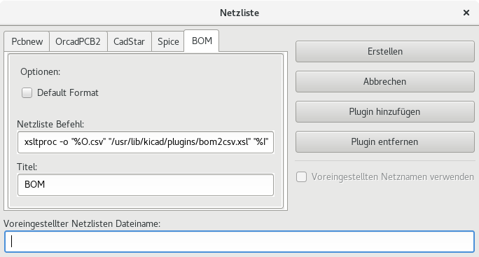
Der Pfad zum Stylesheet bom2csv.xsl ist abhängig vom verwendeten Betriebssystem. Das derzeit beste XSLT Stylesheet zur Stücklistenerzeugung heißt bom2csv.xsl. Sie können es nach Ihren Anforderungen anpassen und wenn Sie etwas allgemein Nutzbares erzeugen, fragen Sie ob es Teil des KiCad Projekts werden kann.
Kommandozeilenformat: Beispiel für Pythonskripte
Das Befehlszeilenformat für Python sieht so aus:
python <script file name> <input filename> <output filename>
Unter Windows:
python *.exe f:/kicad/python/my_python_script.py "%I" "%O"
Unter Linux (wieder abhängig vom Installationsort):
python /usr/local/kicad/python/my_python_script.py "%I" "%O"
Dabei wird angenommen, dass Python auf Ihrem PC installiert ist.
Struktur der Zwischennetzliste
Dieses Beispiel gibt Ihnen eine Idee für das Netzlistendateiformat:
<?xml version="1.0" encoding="utf-8"?>
<export version="D">
  <design>
    <source>F:\kicad_aux\netlist_test\netlist_test.sch</source>
    <date>29/08/2010 21:07:51</date>
    <tool>eeschema (2010-08-28 BZR 2458)-unstable</tool>
  </design>
  <components>
    <comp ref="P1">
      <value>CONN_4</value>
      <libsource lib="conn" part="CONN_4"/>
      <sheetpath names="/" tstamps="/"/>
      <tstamp>4C6E2141</tstamp>
    </comp>
    <comp ref="U2">
      <value>74LS74</value>
      <libsource lib="74xx" part="74LS74"/>
      <sheetpath names="/" tstamps="/"/>
      <tstamp>4C6E20BA</tstamp>
    </comp>
    <comp ref="U1">
      <value>74LS04</value>
      <libsource lib="74xx" part="74LS04"/>
      <sheetpath names="/" tstamps="/"/>
      <tstamp>4C6E20A6</tstamp>
    </comp>
    <comp ref="C1">
      <value>CP</value>
      <libsource lib="device" part="CP"/>
      <sheetpath names="/" tstamps="/"/>
      <tstamp>4C6E2094</tstamp>
    <comp ref="R1">
      <value>R</value>
      <libsource lib="device" part="R"/>
      <sheetpath names="/" tstamps="/"/>
      <tstamp>4C6E208A</tstamp>
    </comp>
  </components>
  <libparts/>
  <libraries/>
  <nets>
    <net code="1" name="GND">
      <node ref="U1" pin="7"/>
      <node ref="C1" pin="2"/>
      <node ref="U2" pin="7"/>
      <node ref="P1" pin="4"/>
    </net>
    <net code="2" name="VCC">
      <node ref="R1" pin="1"/>
      <node ref="U1" pin="14"/>
      <node ref="U2" pin="4"/>
      <node ref="U2" pin="1"/>
      <node ref="U2" pin="14"/>
      <node ref="P1" pin="1"/>
    </net>
    <net code="3" name="">
      <node ref="U2" pin="6"/>
    </net>
    <net code="4" name="">
      <node ref="U1" pin="2"/>
      <node ref="U2" pin="3"/>
    </net>
    <net code="5" name="/SIG_OUT">
      <node ref="P1" pin="2"/>
      <node ref="U2" pin="5"/>
      <node ref="U2" pin="2"/>
    </net>
    <net code="6" name="/CLOCK_IN">
      <node ref="R1" pin="2"/>
      <node ref="C1" pin="1"/>
      <node ref="U1" pin="1"/>
      <node ref="P1" pin="3"/>
    </net>
  </nets>
</export>
Allgemeine Struktur der Netzlistendatei
Die Zwischennetzliste hat fünf Abschnitte.
-
Einen Header Abschnitt.
-
Einen Abschnitt der Bauteile.
-
Einen Abschnitt der Bibliotheksteile.
-
Einen Abschnitt der Bibliotheken.
-
Einen Abschnitt der Netze.
Der Dateiinhalt hat das Trennzeichen <export>.
<export version="D">
...
</export>
Der Header
Der Header hat das Trennzeichen <design>.
<design>
<source>F:\kicad_aux\netlist_test\netlist_test.sch</source>
<date>21/08/2010 08:12:08</date>
<tool>eeschema (2010-08-09 BZR 2439)-unstable</tool>
</design>
Dieser Abschnitt kann als ein Kommentarabschnitt betrachtet werden.
Der Abschnitt der Bauteile
Der Abschnitt der Bauteile hat das Trennzeichen <components>.
<components>
<comp ref="P1">
<value>CONN_4</value>
<libsource lib="conn" part="CONN_4"/>
<sheetpath names="/" tstamps="/"/>
<tstamp>4C6E2141</tstamp>
</comp>
</components>
Dieser Abschnitt enthält die Liste der Bauteile ihres Schaltplans. Jedes Bauteil ist wie folgt beschrieben:
<comp ref="P1">
<value>CONN_4</value>
<libsource lib="conn" part="CONN_4"/>
<sheetpath names="/" tstamps="/"/>
<tstamp>4C6E2141</tstamp>
</comp>
| libsource | name of the lib where this component was found. |
|---|---|
part |
component name inside this library. |
sheetpath |
path of the sheet inside the hierarchy: identify the sheet within the full schematic hierarchy. |
tstamps (time stamps) |
time stamp of the schematic file. |
tstamp (time stamp) |
time stamp of the component. |
Anmerkung zu Zeitstempeln für Bauteile
Um ein Bauteil in einer Netzliste und damit auf der Leiterplatte zu identifizieren, wird die Zeitstempel-Referenz als einzigartig für jedes Bauteil verwendet. Jedoch stellt KiCad einen zusätzlichen Hilfsweg zur Verfügung um ein Bauteil zu identifizieren, und zwar über den zugehörigen Footprint auf der Leiterplatte. Das erlaubt die Neunummerierung von Bauteilen in einem Schaltplanprojekt ohne den Verlust der Verbindung zwischen Bauteil und seinem Footprint.
Ein Zeitstempel ist eine einzigartige Identifizierung für jedes Bauteil oder Blatt in einem Schaltplanprojekt. Jedoch wird in einer komplexen Hierarchie das selbe Blatt mehr als einmal verwendet, daher enthält dieses Blatt Bauteile mit dem gleichen Zeitstempel.
Ein gegebenes Blatt hat eine einzigartige Identifizierung innerhalb einer komplexen Hierarchie: seinen Blattpfad. Ein gegebenes Bauteil (in einer komplexen Hierarchie) hat ebenfalls eine einzigartige Identifizierung: den Blattpfad + seinen Zeitstempel.
Der Abschnitt der Bibliotheksteile
Der Abschnitt der Bibliotheksteile hat das Trennzeichen <libparts> und der Inhalt dieses Abschnitts ist in den Schaltplanbibliotheken festgelegt. Der Abschnitt der Bibliotheksteile enthält:
-
The allowed footprints names (names use wildcards) delimiter <fp>.
-
Die in der Bibliothek definierten Felder, Trennzeichen <fields>.
-
Die Liste der Anschlüsse, Trennzeichen <pins>.
<libparts>
<libpart lib="device" part="CP">
  <description>Condensateur polarise</description>
  <footprints>
    <fp>CP*</fp>
    <fp>SM*</fp>
  </footprints>
  <fields>
    <field name="Reference">C</field>
    <field name="Valeur">CP</field>
  </fields>
  <pins>
    <pin num="1" name="1" type="passive"/>
    <pin num="2" name="2" type="passive"/>
  </pins>
</libpart>
</libparts>
Zeilen wie <pin num="1" type="passive"/> geben ebenfalls den elektrischen Typ des Anschlusses an. Die möglichen elektrischen Typen sind:
Input |
Normaler Eingang |
Output |
Normaler Ausgang |
Bidirectional |
Eingang oder Ausgang |
Tri-state |
Bus Ein-/Ausgang |
Passive |
Üblicherweise die Enden von passiven Bauteilen |
Unspecified |
Unbekannter elektrischer Typ |
Power input |
Spannungseingang des Bauteils |
Power output |
Spannungsausgang wie z.B. Ausgang eines Spannungsreglers |
Open collector |
Offener Kollektorausgang wie häufig in Analog Komparatoren zu finden |
Open emitter |
Ausgang der manchmal bei Logikbausteinen zu finden ist |
Not connected |
Darf im Schaltplan nicht verbunden werden |
Der Abschnitt der Bibliotheken
Der Abschnitt der Bibliotheken hat das Trennzeichen <libraries>. Dieser Abschnitt enthält die Liste der im Projekt verwendeten Schaltplanbibliotheken.
<libraries>
  <library logical="device">
    <uri>F:\kicad\share\library\device.lib</uri>
  </library>
  <library logical="conn">
    <uri>F:\kicad\share\library\conn.lib</uri>
  </library>
</libraries>
Der Abschnitt der Netze
Der Abschnitt der Netze hat das Trennzeichen <nets>. Dieser Abschnitt enthält die "Verbindungen" des Schaltplans.
<nets>
  <net code="1" name="GND">
    <node ref="U1" pin="7"/>
    <node ref="C1" pin="2"/>
    <node ref="U2" pin="7"/>
    <node ref="P1" pin="4"/>
  </net>
  <net code="2" name="VCC">
    <node ref="R1" pin="1"/>
    <node ref="U1" pin="14"/>
    <node ref="U2" pin="4"/>
    <node ref="U2" pin="1"/>
    <node ref="U2" pin="14"/>
    <node ref="P1" pin="1"/>
  </net>
</nets>
Dieser Abschnitt listet alle Netze des Schaltplans auf.
Ein mögliches Netz enthält das folgende:
<net code="1" name="GND">
  <node ref="U1" pin="7"/>
  <node ref="C1" pin="2"/>
  <node ref="U2" pin="7"/>
  <node ref="P1" pin="4"/>
</net>
net code |
ist ein interner Identifikator für dieses Netz |
name |
ist der Name für dieses Netz |
node |
gibt eine Anschlussreferenz an der mit diesem Netz verbunden ist |
Mehr über xsltproc
Finden Sie auf der Seite: http://xmlsoft.org/XSLT/xsltproc.html
Einleitung
xsltproc ist ein Befehlszeilenwerkzeug, um XSLT Stylesheets auf XML Dokumente anzuwenden. Obwohl es als Teil des GNOME-Projekts entwickelt wurde, kann es unabhängig vom GNOME-Desktop verwendet werden.
xsltproc wird von auf Befehlszeile mit dem Namen des zu verwendenden Stylesheets, gefolgt vom Namen der Datei oder Dateien auf welche das Stylesheet angewendet werden soll aufgerufen. Es wird die Standard Eingabe verwenden, wenn ein Dateiname mit - angegeben wird.
Wenn ein Stylesheet in einem XML-Dokument mit Stylesheet Verarbeitungshinweisen enthalten ist, muss kein Stylesheet auf der Befehlszeile angegeben werden. xsltproc wird das enthaltene Stylesheet automatisch erkennen und benutzen. Standardmäßig erfolgt die Ausgabe nach stdout. Sie können eine Ausgabedatei mit der -o Option angeben.
Übersicht
xsltproc [[-V] | [-v] | [-o *file* ] | [--timing] | [--repeat] |
[--debug] | [--novalid] | [--noout] | [--maxdepth *val* ] | [--html] |
[--param *name* *value* ] | [--stringparam *name* *value* ] | [--nonet] |
[--path *paths* ] | [--load-trace] | [--catalogs] | [--xinclude] |
[--profile] | [--dumpextensions] | [--nowrite] | [--nomkdir] |
[--writesubtree] | [--nodtdattr]] [ *stylesheet* ] [ *file1* ] [ *file2* ]
[ *....* ]
Befehlszeilen-Optionen
-V or --version
Zeigt die verwendete Version von libxml und libxslt an.
-v or --verbose
Gebe jeden Schritt aus, den xsltproc bei der Verarbeitung des Stylesheets und des Dokuments durchführt
-o or --output file
Leite die Ausgabe auf den Dateinamen file um. Für mehrere Ausgaben, auch als ``chunking'' benannt, leitet -o Verzeichnis/ die Ausgabendateien in ein spezielles Verzeichnis um. Das Verzeichnis muss schon angelegt sein.
--timing
Zeigt die Zeit an, die für das Lesen des Stylesheets, des Dokuments, Anwenden des Stylesheets und speichern des Ergebnisses benötigt wurde. Die Zeiten werden in Millisekunden angegeben.
--repeat
Führe die Umwandlung 20 mal durch. Wird für Zeit bestimmende Tests verwendet.
--debug
Gibt den XML-Baum des umgewandelten Dokuments aus; für Debug Zwecke.
--novalid
Überspringe das Laden der DTD des Dokuments.
--noout
Das Ergebnis nicht ausgeben.
--maxdepth value
Stellt die maximale Tiefe des Vorlagenstapels ein, bevor libxslt feststellt, dass es in einer unendlichen Schleife festhängt. Der Standard ist 500.
--html
Das Eingabedokument ist eine HTML-Datei.
--param name value
Übergibt einen Parameter mit dem Namen name und des Wertes value an das Stylesheet. Sie können mehrere Namen/Wert Paare bis zu einem Maximum von 32 angeben. Wenn der übergebene Wert eine Zeichenkette und kein Knoten Identifikator ist, benutzen Sie stattdessen --stringparam.
--stringparam name value
Übergibt einen Parameter mit dem Namen name und Wert value wobei value eine Zeichenkette und kein Knoten Identifikator ist. (Anmerkung: die Zeichenkette muss UTF-8 sein.)
--nonet
Nicht das Internet benutzen um DTD’s, Entities oder Dokumente zu laden.
--path paths
Benutze die Liste (getrennt mit Leerzeichen oder Doppelpunkt) von Dateisystempfaden, angegeben über paths, um DTD’s, Entities oder Dokumente zu laden.
--load-trace
Gibt alle während der Verarbeitung geladene Dokumente auf stderr aus.
--catalogs
Benutze den in SGML_CATALOG_FILES spezifizierten SGML-Katalog um den Ort von externen Entities aufzulösen. Standardmäßig sucht xsltproc nach dem Katalog, der in XML_CATALOG_FILES spezifiziert ist. Wenn das nicht spezifiziert ist, benutzt es /etc/xml/catalog.
--xinclude
Verarbeitet das Eingabe-Dokument unter Benutzung der Xinclude-Spezifikation. Mehr Details dazu können in der Xinclude-Spezifikation gefunden werden: http://www.w3.org/TR/xinclude/
--profile --norman
Gibt detaillierte Information über die in jedem Teil des Stylesheets benötigte Zeit aus. Das ist hilfreich um die Performance des Stylesheets zu optimieren.
--dumpextensions
Gibt die Liste aller registrierten Erweiterungen auf stdout aus.
--nowrite
Untersagt jegliches Schreiben in eine Datei oder Ressource.
--nomkdir
Untersagt das Erstellen von Verzeichnissen.
--writesubtree path
Erlaubt das Schreiben von Dateien nur unterhalb des Pfades path.
--nodtdattr
Keine Standardattribute aus dem DTD des Dokuments anwenden.
Xsltproc Rückgabewerte
xsltproc gibt eine Status Nummer zurück, die sehr hilfreich sein kann, wenn es aus einem Skript aufgerufen wird.
0: Normal
1: Kein Argument
2: zu viele Parameter
3: unbekannte Option
4: konnte Stylesheet nicht abarbeiten
5: Fehler im Stylesheet
6: Fehler in einem der Dokumente
7: nicht unterstützte xsl:Ausgabe Methode
8: Zeichenketten-Parameter enthält sowohl einfache als auch doppelte Anführungszeichen
9: interner Verarbeitungsfehler
10: Verarbeitung wurde durch eine Abbruch Nachricht gestoppt
11: konnte das Ergebnis in die Ausgabedatei schreiben
Mehr Information über xsltproc
libxml Webseite: http://www.xmlsoft.org/
W3C XSLT Webseite: http://www.w3.org/TR/xslt
Simulator
Eeschema provides an embedded electrical circuit simulator using ngspice as the simulation engine.
When working with the simulator, you may find the official pspice library useful. It contains common symbols used for simulation like voltage/current sources or transistors with pins numbered to match the ngspice node order specification.
There are also a few demo projects to illustrate the simulator capabilities. You will find them in demos/simulation directory.
Assigning models
Before a simulation is launched, components need to have Spice model assigned.
Each component can have only one model assigned, even if component consists of multiple units. In such case, the first unit should have the model specified.
Passive components with reference matching a device type in Spice notation (R* for resistors, C* for capacitors, L* for inductors) will have models assigned implicitly and use the value field to determine their properties.
| Keep in mind that in Spice notation 'M' stands for milli and 'Meg' corresponds to mega. If you prefer to use 'M' to indicate mega prefix, you may request doing so in the simulation settings dialog. |
Spice model information is stored as text in symbol fields, therefore you may either define it in symbol editor or schematics editor. Open symbol properties dialog and click on Edit Spice Model button to open Spice Model Editor dialog.
Spice Model Editor dialog has three tabs corresponding to different model types. There are two options common to all model types:
Disable symbol for simulation |
When checked the component is excluded from simulation. |
Alternate node sequence |
Allows one to override symbol pin to model node mapping. To define a different mapping, specify pin numbers in order expected by the model. 'Example:'
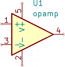
To match the symbol pins to the Spice model nodes shown above, one needs to use an alternate node sequence option with value: "1 3 5 2 4". It is a list of pin numbers corresponding to the Spice model nodes order. |
Passive
Passive tab allows the user to assign a passive device model (resistor, capacitor or inductor) to a component. It is a rarely used option, as normally passive components have models assigned implicitly, unless component reference does not match the actual device type.
| Explicitly defined passive device models have priority over the ones assigned implicitly. It means that once a passive device model is assigned, the reference and value fields are not taken into account during simulation. It may lead to a confusing situation when assigned model value does not match the one displayed on a schematic sheet. |
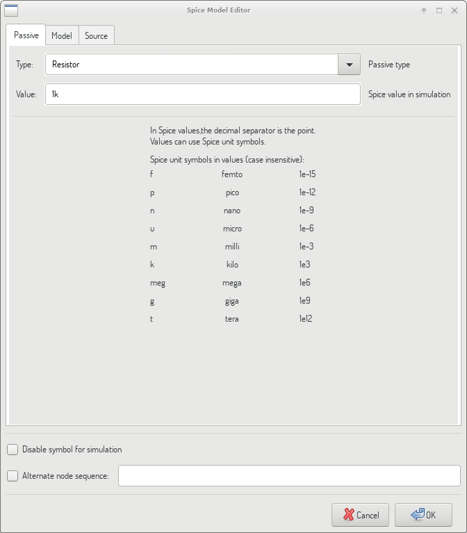
Type |
Selects the device type (resistor, capacitor or inductor). |
Value |
Defines the device property (resistance, capacitance or inductance). The value may use common Spice unit prefixes (as listed below the text input field) and should use point as the decimal separator. Note that Spice does not correctly interpret prefixes intertwined in the value (e.g. 1k5). |
Model
Model tab is used to assign a semiconductor or a complex model defined in an external library file. Spice model libraries are often offered by device manufacturers.
The main text widget displays the selected library file contents. It is a common practice to put models description inside library files, including the node order.
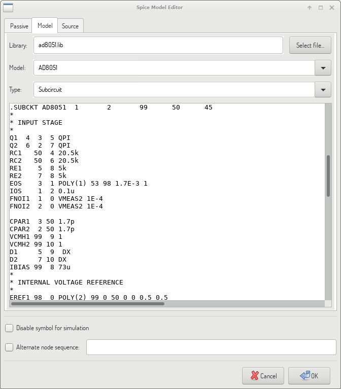
File |
Path to a Spice library file. This file is going to be used by the simulator, as it is added using .include directive. |
Model |
Selected device model. When a file is selected, the list is filled with available models to choose from. |
Type |
Selects model type (subcircuit, BJT, MOSFET or diode). Normally it is set automatically when a model is selected. |
Source
Source tab is used to assign a power or signal source model. There are two sections: DC/AC analysis and Transient analysis. Each defines source parameters for the corresponding simulation type.
Source type option applies to all simulation types.
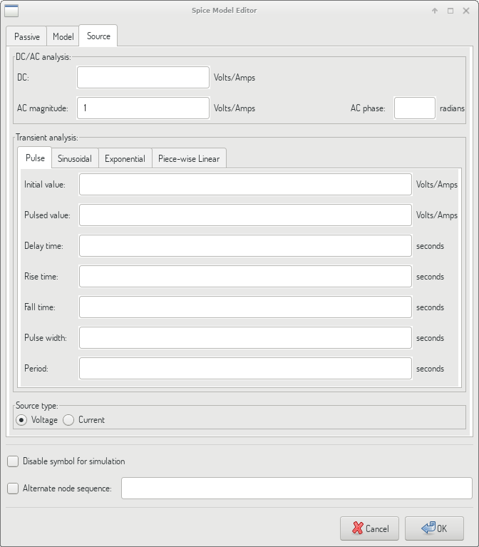
Refer to the ngspice documentation, chapter 4 (Voltage and Current Sources) for more details about sources.
Spice directives
It is possible to add Spice directives by placing them in text fields on a schematic sheet. This approach is convenient for defining the default simulation type. This functionality is limited to Spice directives starting with a dot (e.g. ".tran 10n 1m"), it is not possible to place additional components using text fields.
Simulation
To launch a simulation, open Spice Simulator dialog by selecting menu Tools→Simulator in the schematics editor window.
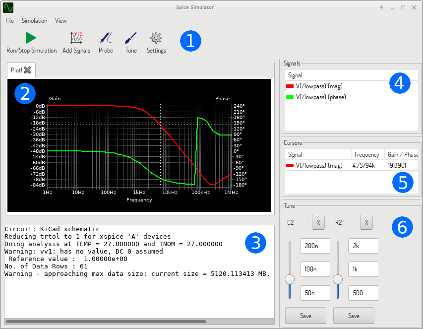
The dialog is divided into several sections:
Menu
File
New Plot |
Create a new tab in the plot panel. |
Open Workbook |
Open a list of plotted signals. |
Save Workbook |
Save a list of plotted signals. |
Save as image |
Export the active plot to a .png file. |
Save as .csv file |
Export the active plot raw data points to a .csv file. |
Exit Simulation |
Close the dialog. |
Simulation
Run Simulation |
Perform a simulation using the current settings. |
Add signals… |
Open a dialog to select signals to be plotted. |
Probe from schematics |
Start the schematics Probe tool. |
Tune component value |
Start the Tuner tool. |
Show SPICE Netlist… |
Open a dialog showing the generated netlist for the simulated circuit. |
Settings… |
Open the simulation settings dialog. |
View
Zoom In |
Zoom in the active plot. |
Zoom Out |
Zoom out the active plot. |
Fit on Screen |
Adjust the zoom setting to display all plots. |
Show grid |
Toggle grid visibility. |
Show legend |
Toggle plot legend visibility. |
Toolbar

The top toolbar provides access to the most frequently performed actions.
Run/Stop Simulation |
Start or stop the simulation. |
Add Signals |
Open a dialog to select signals to be plotted. |
Probe |
Start the schematics Probe tool. |
Tune |
Start the Tuner tool. |
Settings |
Open the simulation settings dialog. |
Plot panel
Visualizes the simulation results as plots. One can have multiple plots opened in separate tabs, but only the active one is updated when a simulation is executed. This way it is possible to compare simulation results for different runs.
Plots might be customized by toggling grid and legend visibility using View menu. When a legend is visible, it can be dragged to change its position.
Plot panel interaction:
-
scroll mouse wheel to zoom in/out
-
right click to open a context menu to adjust the view
-
draw a selection rectangle to zoom in the selected area
-
drag a cursor to change its coordinates
Output console
Output console displays messages from the simulator. It is advised to check the console output to verify there are no errors or warnings.
Signals list
Shows the list of signals displayed in the active plot.
Signals list interaction:
-
right click to open a context menu to hide signal or toggle cursor
-
double click to hide signal
Cursors list
Shows the list of cursors and their coordinates. Each signal may have one cursor displayed. Cursors visibility is set using the Signals list.
Tune panel
Displays components picked with the Tuner tool. Tune panel allows the user to quickly modify component values and observe their influence on the simulation results - every time a component value is changed, the simulation is rerun and plots are updated.
For each component there a few controls associated:
-
The top text field sets the maximum component value.
-
The middle text field sets the actual component value.
-
The bottom text field sets the minimum component value.
-
Slider allows the user to modify the component value in a smooth way.
-
Save button modifies component value on the schematics to the one selected with the slider.
-
X button removes component from the Tune panel and restores its original value.
The three text fields recognize Spice unit prefixes.
Tuner tool
Tuner tool lets the user pick components for tuning.
To select a component for tuning, click on one in the schematics editor when the tool is active. Selected components will appear in the Tune panel. Only passive components might be tuned.
Probe tool
Probe tool provides an user-friendly way of selecting signals for plotting.
To add a signal to plot, click on a corresponding wire in the schematics editor when the tool is active.
Simulation settings
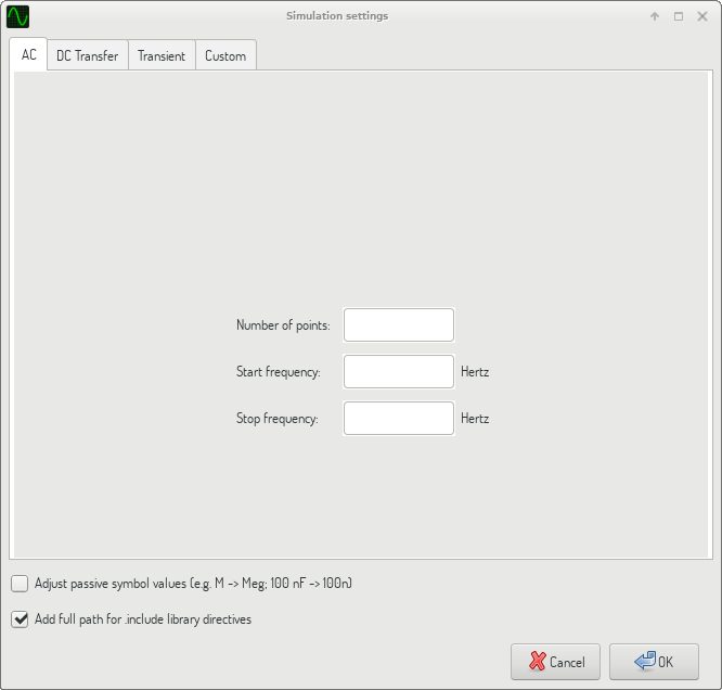
Simulation settings dialog lets the user set the simulation type and parameters. There are four tabs:
-
AC
-
DC Transfer
-
Transient
-
Custom
The first three tabs provide forms where simulation parameters might be specified. The last tab allows the user to type in custom Spice directives to set up a simulation. You can find more information about simulation types and parameters in the ngspice documentation, chapter 1.2.
An alternative way to configure a simulation is to type Spice directives into text fields on schematics. Any text field directives related to simulation type are overridden by the settings selected in the dialog. It means that once you start using the simulation dialog, the dialog overriddes the schematics directives until the simulator is reopened.
There are two options common to all simulation types:
Adjust passive symbol values |
Replace passive symbol values to convert common component values notation to Spice notation. |
Add full path for .include library directives |
Prepend Spice model library file names with full path. Normally full path is required by ngspice to access a library file. |
