符号和符号库
KiCad 将符号组织到符号库中,符号库是符号的集合。原理图中的每个符号都由一个完整的名称作为唯一标识,完整的名称由库的名称和符号名称组成。例如,标识符 Audio:AD1853 是指 Audio 库中的 AD1853 符号。
管理符号库
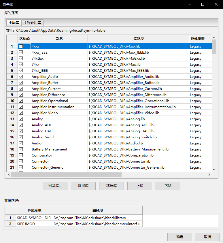
KiCad 使用一个符号库表将符号库名称映射到磁盘上的符号库。 KiCad 使用一个全局的符号库表,以及一个针对每个工程的表。要编辑符号库表,请使用 偏好设置 → 管理符号库…。
全局符号库表包含了无论当前加载的工程是什么,都可以使用的库列表。该表保存在 KiCad 配置文件夹下的 sym-lib-table 文件中。该文件夹的位置 取决于使用的操作系统。
工程专用的符号库表包含了专门为当前加载工程提供的库的列表。如果有任何工程专用的符号库,该表将保存在工程文件夹下的 sym-lib-table 文件中。
KiCad’s symbol library management system allows directly using many types of symbol libraries, including formats that are native to other non-KiCad EDA tools:
-
KiCad symbol libraries (
.kicad_symfiles) -
KiCad Legacy symbol libraries (
.libfiles) -
Altium Designer libraries (
.SchLibor.IntLibfiles) -
CADSTAR Schematic Archive libraries (
.libfiles) -
KiCad database library configuration files (
.kicad_dblfiles) -
Eagle libraries (
.xmlfiles) -
EasyEDA (JLCEDA) Standard Edition libraries (
.jsonfiles) -
EasyEDA (JLCEDA) Professional Edition libraries (
.elibz,.epro, or.zipfiles) -
KiCad HTTP library configuration files (
.kicad_httplibfiles)
Non-KiCad symbol libraries, including KiCad Legacy symbol libraries, can be migrated to KiCad .kicad_sym format using the Migrate Libraries button (see the migrating libraries section).
KiCad only supports writing to KiCad’s native .kicad_sym format symbol libraries. All other symbol library formats are read-only. To modify a non-KiCad format symbol library, you must first convert it to KiCad format.
|
初始配置
The first time the KiCad Schematic Editor is run and the global symbol table file sym-lib-table is not found in the KiCad configuration folder, KiCad will guide the user through setting up a new symbol library table. This process is described above. You can re-run this process at any time by clicking the Reset Libraries.
| Resetting your symbol library table will permanently change your symbol library table on disk. |
管理表格条目
符号库只有在它们被添加到全局或工程专用的符号库表中时才能使用。
通过点击 ![]() 按钮然后选择一个库或点击
按钮然后选择一个库或点击 ![]() 按钮然后输入库文件的路径来添加一个库。选定的库将被添加到当前打开的库表中(全局或特定工程)。可以通过选择所需的库条目并点击
按钮然后输入库文件的路径来添加一个库。选定的库将被添加到当前打开的库表中(全局或特定工程)。可以通过选择所需的库条目并点击 ![]() 按钮来删除库。
按钮来删除库。
The ![]() and
and ![]() buttons move the selected library up and down in the library table. This does not affect the display order of libraries in the Symbol Editor or Symbol Chooser.
buttons move the selected library up and down in the library table. This does not affect the display order of libraries in the Symbol Editor or Symbol Chooser.
通过取消选中第一列中的 Active 复选框,可以使库处于非活动状态。非活动状态的库仍然在库表中,但不会出现在任何库的浏览器中,也不会从磁盘加载,这可以减少加载时间。
通过点击范围内的第一个库,然后 Shift - 点击范围内的最后一个库,可以选择一系列的库。
每个库必须有一个独特的名称:在同一个表中不允许有重复的库名称。然而,名称可以在全局和工程库表中重复。工程表中的库比全局表中的同名库优先级更高。
库的名称不一定要与库的文件名或路径有关。冒号字符(:)不能在库的名称或符号名称中使用,因为它被用作名称和符号之间的分隔符。
Each library entry must have a valid path. Paths can be defined as absolute, relative, or by path variable substitution.
The appropriate library format must be selected in order for the library to be properly read. The supported formats are listed above. Only KiCad format libraries (.kicad_sym) can be saved. Other symbol library formats are read-only and must be converted to KiCad format before you can modify them.
有一个可选的描述字段,用于添加库条目的描述。选项字段目前不使用,所以添加选项在加载库时不会有任何影响。
Path Variable Substitution
The symbol library tables support path variable substitution, which allows you to define path variables containing custom paths to where your libraries are stored. Path variable substitution is supported by using the syntax ${PATH_VAR_NAME} in the symbol library path.
By default, KiCad defines several path variables which are described in the project manager documentation. Path variables can be configured in the Preferences → Configure Paths… dialog.
Using path variables in the symbol library tables allows libraries to be relocated without breaking the symbol library tables, so long as the path variables are updated when the library location changes.
KiCad will automatically resolve versioned path variables from
older versions of KiCad to the value of the corresponding variable from
the current KiCad version, as long as the old variable is not explicitly
defined itself. For example, ${KICAD8_SYMBOL_DIR} will
automatically resolve to the value of ${KICAD9_SYMBOL_DIR} if there
is no KICAD8_SYMBOL_DIR variable defined.
|
${KIPRJMOD} is a special path variable that always expands to the absolute path of the current project directory. ${KIPRJMOD} allows libraries to be stored in the project folder without having to use an absolute path in the project library table. This makes it possible to relocate projects without breaking their project library tables.
使用模式
符号库可以全局定义,也可以专门为当前加载的工程定义。在用户的全局表中定义的符号库总是可用的,并存储在用户的 KiCad 配置文件夹中的 sym-lib-table 文件中。工程专用的符号库表只对当前打开的工程文件有效。
每种方法都有其优点和缺点。在全局表中定义所有的库意味着它们在需要时总是可用的。这样做的缺点是,加载时间会增加。
在工程的基础上定义所有的符号库,意味着你只有工程所需的库,这减少了符号库的加载时间。缺点是你总是要记住添加每个工程所需的每个符号库。
一种使用模式是在全局范围内定义常用的库,并在工程专用的库表中定义工程所需的库。对于如何定义库没有任何限制。
Migrating symbol libraries to KiCad format
Non-KiCad format libraries, including legacy libraries (.lib files), are read-only. They need to be converted to KiCad format (.kicad_sym files) before you can save changes to them.
| As with most KiCad files, newer versions of KiCad can open older-format library files, but older versions of KiCad cannot read files once they have been saved by a newer version of KiCad. |
Libraries in other formats can be converted to KiCad libraries by selecting them in the symbol library table and clicking the Migrate Libraries button. Multiple libraries can be selected and migrated at once by Ctrl-clicking or shift-clicking.
也可以一次转换一个库,方法是在符号编辑器中打开它们并将它们另存为新库。
遗留工程重新映射
当加载在符号库表实现之前创建的原理图时,KiCad 将尝试将原理图中的符号库链接重新映射到适当的库表符号。 这个过程的成功与否取决于几个因素:
-
原理图中使用的原始库仍然可用,并且与符号被添加到原理图中时相比没有变化。
-
所有恢复操作都是在检测到创建恢复库或保持现有恢复库最新时进行的。
-
工程符号缓存库的完整性没有被破坏。
|
重新映射将在工程文件夹中的 |
|
即使恢复操作已被禁用,也会被执行,以确保正确的符号可用于重新映射。 不要取消这个操作,否则重新映射将不能正确地重新映射原理图符号。 任何错误的符号链接将不得不手动修复。 |
|
如果原来的库已经被删除,并且没有进行恢复,作为最后的手段,缓存库可以作为恢复库使用。将缓存库复制到一个新的文件名,并使用符号库表实现之前的 KiCad 版本将新的库文件添加到库列表的顶部。 |
创建和编辑符号
符号是一个元件的在原理图上的表述。一个符号由以下部分组成:
-
图形对象(直线、圆形、圆弧、文字等),决定了符号在原理图中的外观。
-
引脚,具有图形属性(直线、时钟、反相、低电平有效等)和电气属性(输入、输出、双向等),由电气规则检查(ERC)工具使用。
-
字段,如位号、值、PCB 设计的对应封装名称等。
A symbol library is composed of one or more symbols. Generally the symbols are logically grouped by function, type, and/or manufacturer. Each symbol library is a single file with the .kicad_sym extension.
符号可以从同一库中的另一个符号衍生出来。派生符号共享基础符号的图形形状和引脚定义,但可以覆盖基础符号的属性字段(值、封装、封装筛选器、数据手册、描述等)。派生符号可用于定义与基本部件相似的符号。例如,74LS00、74HC00 和 7437 符号都可以从 7400 符号衍生出来。在以前的 KiCad 版本中,派生符号被称为别名。
符号编辑器概述
KiCad provides a symbol editing tool that allows you to create libraries; add, edit, delete, or transfer symbols between libraries; export symbols to files; and import symbols from files. The Symbol Editor can be launched from the KiCad Project Manager or from the Schematic Editor (Tools → Symbol Editor). You can also open the Symbol Editor from the a symbol in the schematic; in this way you can edit either the library copy or the schematic copy of that symbol in the editor.
| Editing the library version of a symbol will not affect any copies of that symbol that have been added to a schematic until the schematic copy is updated from the library. Conversely, editing the schematic version of a symbol will not affect the library version of a symbol or any other copies of that symbol in a schematic. |
一般来说,设计一个符号的流程包括:
-
定义符号是否由一个或多个单元组成。
-
定义符号是否有替代的主体风格(也称为德摩根代号)。
-
使用直线、矩形、圆形、多边形和文字设计其符号外观。
-
添加引脚,并仔细定义每个引脚的图形元素、名称、编号和电气属性(输入、输出、三态、电源输出等)。
-
确定该符号是否应从另一个具有相同图形设计和引脚定义的符号中衍生出来。
-
添加可选的字段,如 PCB 设计软件使用的封装名称和/或定义其可见性。
-
通过添加描述字符串和数据手册链接来记录该符号,等等。
-
将其保存在所需的库中。
The Symbol Editor main window is shown below. It has three toolbars for quick access to common features and a symbol viewing/editing canvas. Not all commands are available on the toolbars, but all commands are available in the menus.
In addition to the toolbars, there are collapsible panels for the symbol tree, Properties Manager, and selection filter on the left. The bottom of the window contains a message panel that shows details about the selected object.
Top toolbar
主工具栏位于主窗口的顶部。工具栏的按钮包括撤销/重做命令、缩放命令、符号属性对话框和单元外观管理控制等。
|
Create a new symbol in the selected library. |
|
Save the currently selected library. All modified symbols in the library will be saved. |
|
Undo last edit. |
|
Redo last undo. |
|
Refresh display. |
|
Zoom in. |
|
Zoom out. |
|
Zoom to fit symbol in display. |
|
Zoom to fit selection. |
|
Rotate counter-clockwise. |
|
Rotate clockwise. |
|
Mirror horizontally. |
|
Mirror vertically. |
|
Edit the current symbol’s properties. |
|
Edit the symbol’s pins in a tabular interface. |
|
Open the symbol’s datasheet, if it is defined. |
|
Run the symbol checker to test the current symbol for design errors. |
|
Select the normal body style. The button is disabled if the current symbol does not have an alternate body style. |
|
Select the alternate body style. The button is disabled if the current symbol does not have an alternate body style. |
|
Select the unit of a multi-unit symbol to display. The drop down control will be disabled if the current symbol does not have multiple units. |
|
Enable synchronized pin edit mode. When this mode is enabled, any pin modifications are propagated to all other symbol units. Pin number changes are not propagated. This mode is automatically enabled for symbols with multiple interchangeable units and cannot be enabled for symbols with only one unit. |
|
Insert current symbol into the schematic. |
左侧工具栏显示控制
The left toolbar provides options to change the display of items in the Symbol Editor.
|
Toggle grid visibility on and off. |
|
Toggle item-specific grid overrides on and off. |
|
Set units to inches, mils (0.001 inch), or millimeters. |
|
Toggle full screen cursor on and off. |
|
Toggle display of pin electrical types. |
|
Toggle display of hidden (invisible) pins. |
|
Toggle display of hidden (invisible) fields. |
|
Toggle display of library and symbol tree. |
|
Toggle display of Properties Manager panel. |
Right toolbar tools
Placement and drawing tools are located in the right toolbar.
|
Select tool. Right-clicking with the select tool opens the context menu for the object under the cursor. Left-clicking with the select tool displays the attributes of the object under the cursor in the message panel at the bottom of the main window. Double-left-clicking with the select tool will open the properties dialog for the object under the cursor. |
|
Pin tool. Left-click to add a new pin. |
|
Graphical text tool. Left-click to add a new graphical text item. |
|
Graphical textbox tool. Left-click to add a new graphical textbox item. |
|
Rectangle tool. Left-click to begin drawing the first corner of a graphical rectangle. Left-click again to place the opposite corner of the rectangle. |
|
Circle tool. Left-click to begin drawing a new graphical circle from the center. Left-click again to define the radius of the circle. |
|
Arc tool. Left-click to begin drawing a new graphical arc item from the first arc end point. Left-click again to define the second arc end point. Adjust the radius by dragging the arc center point. |
|
Bezier curve tool. Left-click to begin drawing a new graphical bezier curve item. First click for the start point, then for the control points and the end point. Adjust the curve by dragging the points. |
|
Connected line tool. Left-click to begin drawing a new graphical line item in the current symbol. Left-click for each additional connected line. Double-left-click to complete the line. |
|
Connected line tool. Left-click to begin drawing a new graphical line item in the current symbol. Left-click for each additional connected line. Double-left-click to complete the line. |
|
Anchor tool. Left-click to set the anchor position of the symbol. |
|
Delete tool. Left-click to delete an object from the current symbol. |
Browsing, modifying, and saving symbols
The ![]() button displays or hides the list of available libraries, which allows you to select an active library. When a new symbol is created, it will be placed in the active library.
button displays or hides the list of available libraries, which allows you to select an active library. When a new symbol is created, it will be placed in the active library.
Clicking on a symbol name opens that symbol in the editor, and hovering the cursor over the name of a symbol displays a preview of the symbol.
| 有些符号是由其他符号衍生出来的。派生的符号名称在树状图中以 大写字母 显示。如果一个派生符号被打开,它的符号图形将不能被编辑。它的符号字段将可以正常编辑。要编辑一个基本符号及其所有衍生符号的图形,请打开基本符号。 |
After modification, a symbol can be saved in the current library or a different library. To save the modified symbol in the current library, click the ![]() icon.
icon.
| 保存一个修改过的符号也会保存同一库中所有其他修改过的符号。 |
To save the symbol changes to a new symbol, click File → Save As…. The symbol can be saved in the current library or a different library (including a new library), and a new name can be set for the symbol. Alternatively, you can use File → Save Copy As…, which behaves the same as Save As except that the original symbol remains open rather than switching to the new symbol.
To create a new file containing only the current symbol, click File → Export → Symbol…. This file will be a standard symbol library file which will contain only one symbol. The library will not be added to your library table.
The editor can also open symbols from the schematic. To edit a symbol from the schematic, right click a symbol in the Schematic Editor and select Open in Schematic Editor (Ctrl+E).
Editing and saving the schematic copy of a symbol will only update that symbol in the schematic; it will not update other copies of that symbol in the schematic, and it will not change the original library copy of the symbol. When you open the schematic copy of a symbol, the Schematic Editor displays an info bar that warns you the library copy will not be modified. You can click the link in this info bar to open the library version of the symbol instead, or press Ctrl+Shift+E.
Creating a new symbol library
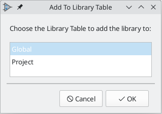
You can create a new symbol library by clicking File → New Library…. At this point you must choose whether the new library should be added to the global symbol library table or the project symbol library table. Libraries in the global library table will be available to all projects, while libraries in the project library table will only be available in the current project.
Following selection of the library table, you must choose a name and location for the new library. A new, empty library will be created at the specified location.
创建一个新符号
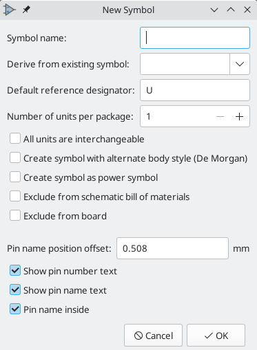
To create a new symbol in the current symbol library, click the ![]() button. You will be asked for a number of symbol properties.
button. You will be asked for a number of symbol properties.
-
符号名称
-
一个可选的基础符号,用于派生新的符号。新符号将使用基础符号的图形形状和引脚配置,但其他符号信息可以在派生符号中修改。基础符号必须与新派生符号在同一个库中。
-
位号前缀(
U,C,R)。 -
每个符号的单元数,以及这些单元是否可以互换(例如,一个 7400 四路 NAND 符号可以有 4 个单元,每个门一个)。
-
是否需要另一种主体样式(有时被称为 "德-摩根等价")。
-
Whether the symbol is a power symbol. Power symbols appear in the Add Power Symbol dialog in the Schematic editor, make global net connections based on their value, cannot be assigned a footprint, and are excluded from the PCB and bill of materials.
-
该符号是否应从物料清单中排除。
-
该符号是否应从 PCB 中排除。
还有几种图形选项。
-
每个引脚的末端和它的引脚名称之间的偏移。
-
是否应显示引脚编号和引脚名称。
-
引脚名称是否应显示在引脚旁边,或显示在符号主体内的引脚末端。
这些属性以后也可以在符号属性窗口中修改。
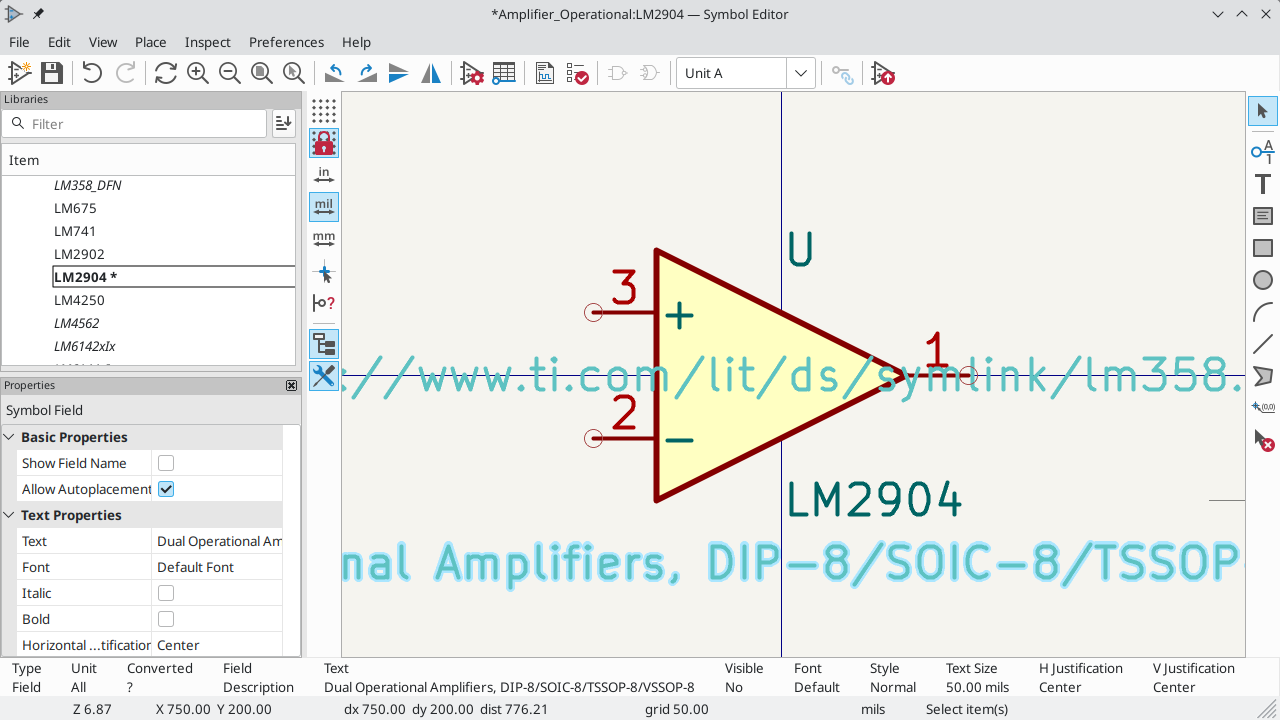
一个新的符号将使用上述属性被创建,并将出现在编辑器中,如下图所示。
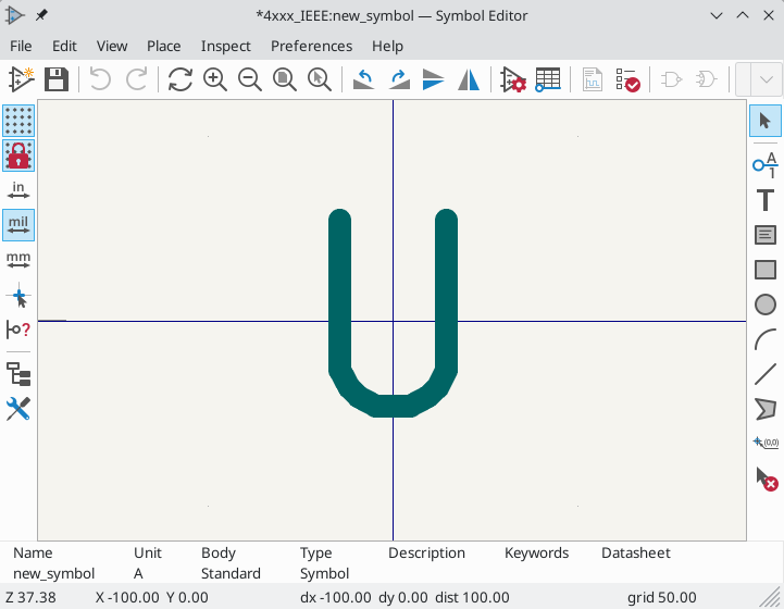
The blue cross in the center is the symbol anchor, which specifies the symbol origin i.e. the coordinates (0, 0). The anchor can be repositioned by selecting the ![]() button and clicking on the new desired anchor position.
button and clicking on the new desired anchor position.
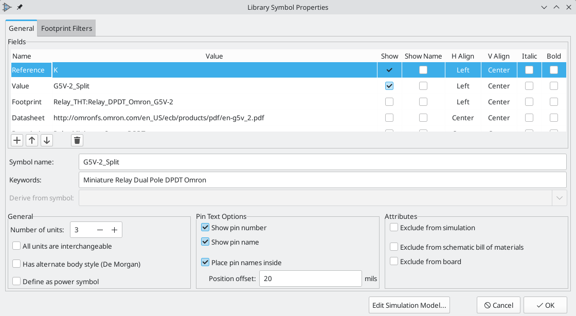
Editing Symbol Properties
符号属性是在创建符号时设置的,但它们可以在任何时候被修改。要改变符号属性,请点击 ![]() 图标,显示符号属性对话框。你也在编辑画布中空白位置双击打开属性对话框。
图标,显示符号属性对话框。你也在编辑画布中空白位置双击打开属性对话框。
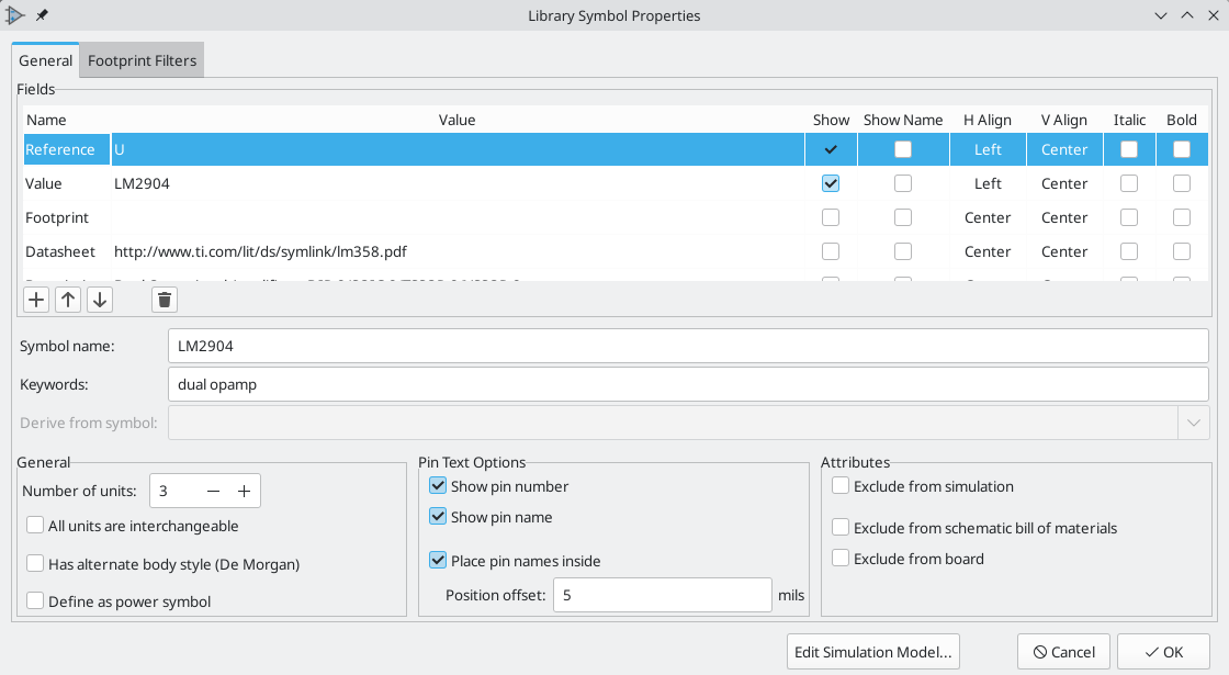
设置 单元数量,并检查 所有单元都可互换 和 具有交替的主体风格(如适用)是很重要的,因为这些设置会影响引脚和图形被添加到每个符号单元的方式。
如果你在向符号添加引脚后再改变符号的单元数,你将需要做额外的工作来为额外的单元添加引脚和图形。如果最初正确设置了这些属性,引脚和图形就会自动添加到每个单元。尽管如此,还是可以在任何时候修改这些属性。
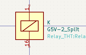
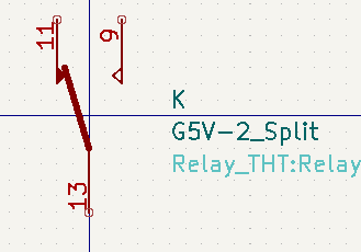
图形选项 显示引脚编号 和 显示引脚名称 用来定义引脚编号和引脚名称文本的可见性。选项 将引脚名称置于内部 定义了引脚名称相对于引脚主体的位置。如果该选项被选中,引脚名称将被显示在符号的轮廓内。在这种情况下,引脚名称位置偏移 属性定义了文字远离引脚末端的位置。通常,0.02 到 0.05 英寸是合理的。
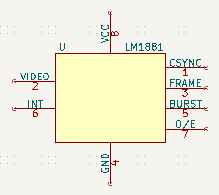
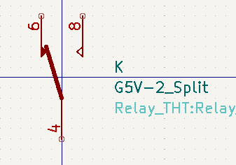
下面的例子显示了一个没有勾选 将引脚名称置于内部 选项的符号。注意名称和引脚编号的位置。
Symbol Name and Keywords
Symbol name is the symbol’s name in the library. Symbols are identified by a combination of the library and symbol name.
在以前的 KiCad 版本中,符号名称与 值 字段相连。 在 KiCad 7.0 及以后的版本中,这种联系被删除。
The keywords should contain additional terms related to the component. Keywords are primarily used, in combination with the symbol name and the Description field, for searching for the symbol in the Symbol Chooser and the Symbol Editor. Those three items are also displayed when you select a symbol in the Symbol Chooser.
符号字段
Symbols contain multiple fields, which are named values containing information related to the symbol. Fields can be displayed on the schematic or hidden and only shown in the symbol’s properties. Some fields have special meaning to KiCad: Reference and Footprint are both critical for creating a PCB, for example. Other fields may contain information that is important for a design but is not interpreted by KiCad, like pricing or stock information for a part.
Any fields defined in a library symbol will be included in the symbol when it is added to a schematic. You can also add new fields to symbols in the schematic. Whether they are in the library symbol or not, these fields can then be edited on a per-symbol basis in the schematic. They are also transferred to the symbol’s corresponding footprint in the PCB.
| Symbol fields are different than graphic text. In addition to being named, fields can be moved and edited in the schematic, while symbol text can only be edited in the symbol editor. |
All library symbols are defined with five default fields: Reference, Value, Footprint, Datasheet, and Description, which are added whenever a symbol is created. These default fields cannot be deleted. Only the Reference field is required to have a value: the contents of a library symbol’s Reference field is used as the reference designator prefix when the symbol is added to a schematic. In the schematic, the symbol’s Reference field contains the entire reference designator.
如果使用 封装 字段,则包含符号与封装关联。格式是 LIBNAME:FOOTPRINTNAME,其中 LIBNAME 是封装库表中的封装库名称(见 PCB 编辑器手册中的 封装库表部分),FOOTPRINTNAME 是 LIBNAME 库中的封装名称。
The Description field can contain text describing the symbol such as the component function, distinguishing features, and package options. Together with the symbol’s name and keywords, text in this field is used when searching for symbols in the Symbol Chooser or Symbol Editor. Before KiCad version 8.0, this was a dedicated property (like the symbol name and keywords) rather than a symbol field.
Symbols defined in libraries are typically defined with only these five default fields. Additional fields such as vendor, part number, unit cost, etc. can be added to library symbols but generally this is done in the schematic editor so the additional fields can be added to every symbol in the schematic, not just all symbols of one type.
| 创建额外的空符号字段的一种便捷方法是使用定义字段名称模板。字段名称模板定义空字段,当每个符号插入原理图时,这些字段会被添加到每个符号中。字段名称模板可以在原理图编辑器首选项中全局定义(针对所有原理图),也可以在原理图设置对话框中局部定义(针对每个工程)。 |
| 如果你想在符号字段中管理大量的元件数据,可以考虑使用数据库关联库。 |
要编辑一个现有的符号字段,请双击该字段,选择它或悬停并按 E,或右击字段文本并选择 属性…。
To add new fields, delete optional fields, or edit existing fields, use the ![]() icon on the main tool bar to open the Symbol Properties dialog. Fields can be arbitrarily named, but names starting with
icon on the main tool bar to open the Symbol Properties dialog. Fields can be arbitrarily named, but names starting with ki_, e.g. ki_description, are reserved by KiCad and should not be used for user fields.
Fields have a number of properties, each of which is shown as a column in the properties grid. Not all columns are shown by default; columns can be shown or hidden by right clicking on the grid header and selecting or deselecting columns from the menu.
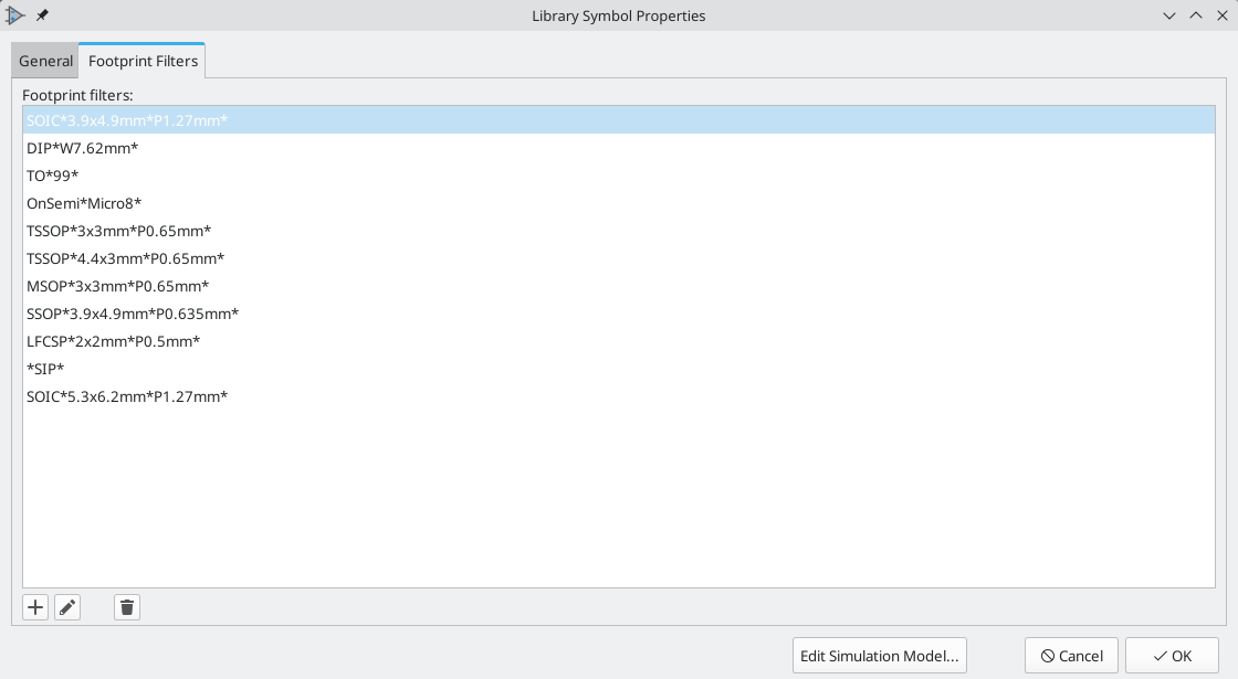
Footprint Filters
封装筛选器标签用于定义哪些封装适合与符号一起使用。筛选器可以在封装分配工具中使用,以便只显示每个符号合适的封装。
可以定义多个封装筛选器。符合任何一个筛选器的封装将被显示;如果没有定义筛选器,那么所有的封装都将被显示。
筛选器可以使用通配符。* 匹配任何数量的字符,包括零,而 ? 匹配零或一个字符。例如,SOIC-* 将匹配 SOIC-8_3.9x4.9mm_P1.27mm 封装以及任何其他以 SOIC- 开头的封装。筛选器 SOT?23 匹配 SOT23 以及 SOT-23。
Embedding files
External files can be embedded within a symbol. Embedding a file stores a copy of the file inside the symbol. The symbol can then refer to the embedded copy of the file instead of the external file, which makes the symbol more portable as it doesn’t rely on an external file, although the symbol library’s filesize is increased as a result. In symbols this is especially useful for embedding datasheets and SPICE models. Files embedded in a symbol are deduplicated when the symbol is added to a schematic: if a file is embedded in a symbol, and multiple instances of that symbol are added to the schematic, only one copy of the file will be embedded, and all of the schematic instances will refer to the same embedded file. Files embedded in a schematic cannot be referred to in the parent schematic. File embedding is explained in more detail in the Schematic Setup documentation.
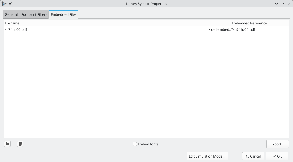
| You can add a datasheet, or a SPICE model, to a symbol and embed it in one step. To do so, browse for a datasheet (in the Symbol Properties dialog) or a SPICE model (in the SPICE Model Editor) and enable the Embed File checkbox in the file browser while choosing a file. This embeds the file and automatically uses the embedded reference as the file path instead of the path to the external file. |
Symbol Units and Alternate Body Styles
Symbols can have more than one unit per package, each with different graphics and pin configurations. This is often used for logic gates, opamps, or other components that have multiple subunits within one physical package. Symbols can also have up to two body styles, a standard symbol and an alternate symbol often referred to as a "De Morgan equivalent".
For example, consider a relay with two switches, which can be designed as a symbol with one body style and three different units: a coil, switch 1, and switch 2. Designing a symbol with multiple units per package and/or alternate body styles is very flexible. A pin or a body symbol item can be common to all units or specific to a given unit or they can be common to both symbolic representation so are specific to a given symbol representation.
By default, pins are specific to a unit and body style. When a pin is common to all units or all body styles, it only needs to be created once, no mattery how many units or body styles are used. This is also the case for the body style graphic shapes and text, which may be common to each unit, but typically are specific to each body style.
要向一个符号添加额外的单元,在符号属性对话框中将 单元数量 属性设置为适当的数字。默认情况下,符号单元被命名为 单元 A、单元 B 等,但你可以使用 编辑 → 设置单元显示名称… 为当前单元设置一个任意的名称。
Use the  unit selection dropdown to select the unit you wish to edit.
要添加一个备用的主体样式,请在符号属性对话框中设置 存在备用的主体样式(德摩根) 属性。
If the symbol has an alternate body style defined, one body style must be selected for editing at a time. To edit the normal representation, click the ![]() icon. To edit the alternate representation, click on the
icon. To edit the alternate representation, click on the ![]() icon.
icon.
|
Synchronized Pins Edit Mode can be enabled by clicking the
|
Symbol Graphics
Graphical elements create the visual representation of a symbol and contain no electrical connection information. You can draw new graphic shapes using the buttons on the right toolbar. The following types of objects are available:
-
Lines (
 ) and polygons (
 ) defined by start and end points.
 -
Rectangles (
 ) defined by two diagonal corners.
 -
Circles (
 ) defined by the center and radius.
 -
Arcs (
 ) defined by the starting and ending point of the arc and its center.
 -
Graphical text (
 ) and textboxes (
 ), which is automatically oriented to be readable, even when the symbol is mirrored. Note that graphic text items are not the same as symbol fields.
Each graphic item (line, arc, circle, etc.) can be defined as common to all units and/or body styles or specific to a given unit and/or body style.
Element options can be quickly accessed by right-clicking on the element to display the context menu for the selected element. You can also double-left-click on an element to modify its properties, or edit its properties using the Properties Manager panel.
Below is the properties dialog for a polygon element.
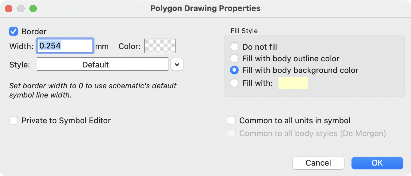
图形元素的属性是:
-
Border determines whether the the shape’s outline should be drawn.
-
Width and color define the line width and color of the border. A border width of
0uses the schematic’s default symbol line width. Style determines the line style of the border (solid, dashed, dotted, etc.). -
Fill Style determines if the shape defined by the graphical element is to be drawn unfilled or filled. The fill color can be the color theme’s body outline color, body background color, or a custom color.
-
Common to all units in symbol determines if the graphical element is drawn for each unit in symbol with more than one unit per package or if the graphical element is only drawn for the current unit.
-
Common to all body styles (De Morgan) determines if the graphical element is drawn for each symbolic representation in symbols with an alternate body style or if the graphical element is only drawn for the current body style.
-
Private to Symbol Editor causes the shape to be visible only when the symbol is edited in the Symbol Editor. The shape will be hidden when the symbol is added to a schematic.
符号引脚
可以点击 ![]() 按钮来创建和插入一个引脚。可以通过双击引脚来编辑引脚的属性。也可以删除或移动你已经添加的引脚。必须小心地创建引脚,因为任何错误都会对 PCB 设计产生影响。
按钮来创建和插入一个引脚。可以通过双击引脚来编辑引脚的属性。也可以删除或移动你已经添加的引脚。必须小心地创建引脚,因为任何错误都会对 PCB 设计产生影响。
一个引脚是由它的图形表示、名称和编号定义的。引脚的名称和编号可以包含字母、数字和符号,但不能包含空格。 为了使电气规则检查(ERC)工具发挥作用,引脚的电气类型(输入、输出、三态…)也必须被正确定义。如果这个类型定义不正确,原理图上的 ERC 检查结果可能是无效的。
要点:
-
符号的引脚按编号与封装的焊盘相匹配。符号中的引脚编号必须与封装中相应的焊盘编号相对应。
-
不要在引脚名称和数字中使用空格。空格将被自动替换成下划线(
_)。 -
要定义带有反转信号(上划线)的引脚名称,请使用
~(波浪号)字符后跟文本以在大括号中反转。 例如~{FO}O会显示 FO O。 -
如果引脚名称为空,则认为该引脚未被命名。
-
引脚名称可以在一个符号中重复。
-
引脚编号在一个符号中必须是唯一的。
引脚属性
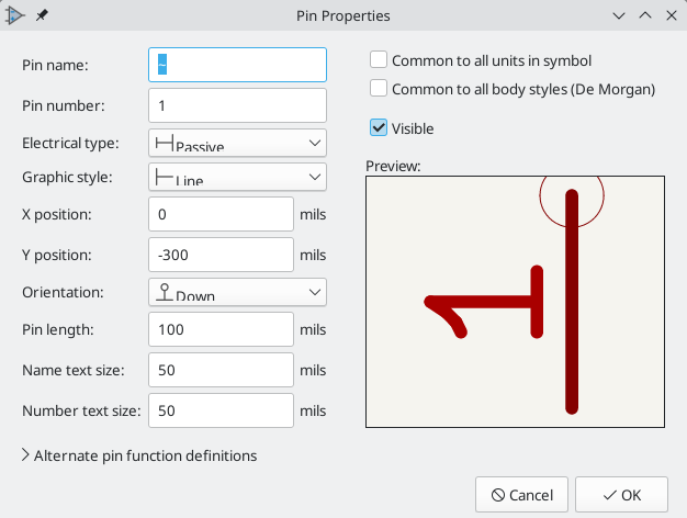
引脚属性对话框允许你编辑引脚的所有属性。当你创建一个引脚或双击一个现有的引脚时,这个对话框会自动弹出。对话框允许你修改:
-
引脚名称和文字大小。
-
引脚编号和文字大小。
-
引脚的长度。
-
引脚的电气类型和图形风格。
-
单元和备用主体。
-
引脚可见性。
-
《备用引脚定义,备用引脚定义》。
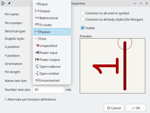
引脚电气类型
Each pin in a symbol has an electrical type, such as input, output, or tri-state.
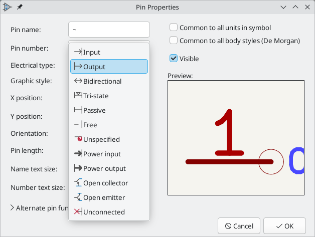
选择正确的电气类型对原理图 ERC 工具很重要。 ERC 将检查引脚的连接是否恰当,例如,确保输入引脚被驱动,电源输入从适当的来源接收电源。
You can use the Pin Conflicts Map in the schematic editor to configure which pin types are allowed to connect and which will conflict. The default Pin Conflicts settings are briefly explained below. For more information, see the ERC documentation.
Additionally, some pin types have special behavior outside of ERC. In the router, pads corresponding to a free pin can be connected to copper of any other net without causing a DRC error, and multiple pads corresponding to a single unconnected pin do not need to be connected to each other in the board.
| The pin type that produces the optimal ERC pin conflict checking behavior is not always the same as the pin’s conceptual pin type. When selecting a pin type, you should consider how that type will interact with the pin type of other connected pins and whether that will result in the desired ERC behavior. An example is an analog control pin that generates a current and senses the voltage generated by that current flowing through an external resistor. This pin could be considered an input pin because it senses a voltage provided externally. However, in a schematic this pin will be connected to a resistor pin (passive) and not to an output pin. There shouldn’t be an ERC violation if the pin isn’t connected to an output pin; in fact, there should be an ERC violation if the pin does connect to another output pin, as the pin would be sourcing a current on a net that is already driven. Therefore such a pin should have the Output pin type even though it is sensing a voltage and could be considered an input. |
Pin Type |
Description |
Input |
A pin which is exclusively an input. The default Pin Conflicts settings allow input pins to connect to most other types of pin. Also, an ERC violation will be produced if an input pin is not driven, i.e. it is not connected to a pin with type output, bidirectional, tristate, power output, or passive. |
Output |
A pin which is exclusively an output. The default Pin Conflicts settings allow output pins to connect to most types of pin that aren’t also outputs. |
Bidirectional |
A pin that can be either an input or an output, such as a microcontroller data bus pin. The default Pin Conflicts settings allow bidirectional pins to connect to most other types of pins, though there are a few more restrictions than with input pins. |
Tri-state |
A three state output pin (high, low, or high impedance). The default Pin Conflicts settings allow tri-state pins to connect to most other types of pins, but warnings are generated when they are connected to most types of output or power pins. |
Passive |
A pin that is not connected to active electronics, for example pins on a resistor or connector. The default Pin Conflicts settings allow passive pins to connect to most other types of pin. |
Free |
A pin that does not electrically affect the operation of the device. These pins typically represent package leads that are not internally connected to the chip. The default Pin Conflicts settings allow free pins to connect to most other types of pin. In the PCB editor, pads corresponding to free pins can be connected to copper of any other net without causing a DRC error. |
Unspecified |
A pin which has an unspecified type. With the default Pin Conflicts settings, ERC generates warnings when unspecified pins are connected to most other types of pins. |
Power input |
A pin that powers the device. The default Pin Conflicts settings allow power input pins to connect to most other pin types. However, power input pins that are not connected to a power output pin generate an ERC violation. Additionally, power input pins that are marked invisible are automatically connected to the net with the same name as the pin. This behavior is supported primarily for legacy projects and is not recommended for new designs. See the Hidden Power Pin section for more information. |
Power output |
A pin that provides power to other pins, such as a regulator output. The default Pin Conflicts settings allow power output pins to connect to most types of input pins, but not output pins. |
Open collector |
An open collector logic output. The default Pin Conflicts settings allow open collector pins to connect to most input pins and other open collector pins, but not to most other types of outputs. |
Open emitter |
An open emitter logic output. The default Pin Conflicts settings allow open collector pins to connect to most input pins and other open emitter pins, but not to most other types of outputs. |
Unconnected |
A pin that should not be connected to anything. ERC does not allow pins of type unconnected to connect to any other type of pin, and ERC will not generate an "unconnected pin" violation when pins of this type are left unconnected. Unconnected pins are not configurable in the ERC Pin Conflicts map. If a footprint has multiple pads corresponding to a single unconnected pin, the pads do not need to be connected to each other in the board. When multiple pins of type unconnected are stacked in a symbol, they are connected to separate nets, whereas stacked pins of other types are connected to the same net. Note that this pin type is different than placing a no connect flag on a pin in the schematic. The unconnected pin type indicates that the pin should never be connected in any schematic, while a no connect flag indicates that the pin is intentionally unconnected in the current schematic. |
将引脚属性推送到其他引脚
你可以通过右击一个引脚,并分别选择 推送引脚长度、推送引脚名称大小 或 推送引脚编号大小,将该引脚的长度、名称大小或数字大小应用于符号中的其他引脚。符号中的所有其他引脚将被更新。
为多个单元和备用主体样式定义引脚
Symbols with multiple units and/or graphical representations are particularly problematic when creating and editing pins. Most commonly, pins are specific to each symbol unit (because each unit has a different set of pins) and to each body style (because the form and position is different between the normal body style and the alternate form).
符号库编辑器允许同时创建引脚。默认情况下,对引脚所做的修改是针对一个多单元符号的所有单元,以及对具有替代符号主题样式的两种表示法。 唯一的例外是引脚的图形类型和名称,它们在符号单元和主体样式之间保持无关联。建立这种依赖关系是为了在大多数情况下更容易创建和编辑引脚。这个依赖关系可以通过切换主工具栏上的 ![]() 图标来禁用。这将允许你完全独立地为每个单元和代表创建引脚。
图标来禁用。这将允许你完全独立地为每个单元和代表创建引脚。
引脚可以是共用的,也可以是不同单元所特有的。引脚可以是两个符号主体样式共有的,也可以是每个符号主体特有的。当一个引脚对所有单元都通用时,它只需要绘制一次。引脚可以在引脚属性对话框中设置为通用或特定。
一个例子是 7400 四路双输入 NAND 门的输出引脚。由于有四个单元和两个符号表示,在符号定义中有八个独立的输出引脚。当创建一个新的 7400 符号时,常用主体样式的单元 A 将显示在库编辑器中。要编辑备用主体样式中的引脚,必须首先通过点击工具栏上的 ![]() 按钮切换到备用样式。要编辑各个单元的引脚编号,请使用 下拉控件选择合适的单元。
按钮切换到备用样式。要编辑各个单元的引脚编号,请使用 下拉控件选择合适的单元。
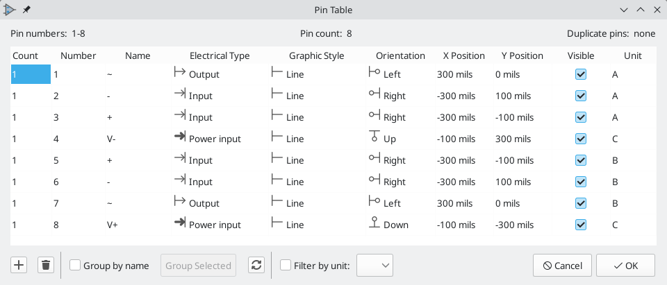
引脚表
另一种编辑引脚的方法是使用引脚表,可以通过 ![]() 图标访问。引脚表以表格的形式显示符号中的所有引脚及其属性,所以它对批量修改引脚很有用。
图标访问。引脚表以表格的形式显示符号中的所有引脚及其属性,所以它对批量修改引脚很有用。
任何引脚属性都可以通过点击相应的单元格进行编辑。可以用 ![]() 和
和 ![]() 图标分别添加和删除引脚。
图标分别添加和删除引脚。
可以通过分组来同时编辑多个引脚的同一属性。 引脚可以按名称自动分组,也可以通过选择几个引脚并点击 选择的分组 来手动分组。点击 ![]() 按钮来清除手动分组。 你也可以过滤表格,只显示某些单元的引脚。
按钮来清除手动分组。 你也可以过滤表格,只显示某些单元的引脚。
| 通过右键单击标题行并勾选或取消附加列,可以显示或隐藏引脚表的各列。有些列是默认隐藏的。 |
The screenshot below shows the pin table for a dual opamp.
Alternate Pin Function Definitions
Symbol pins can have alternate pin functions defined for them. Alternate pin functions allow you to select a different name, electrical type, and graphical style for a pin when a symbol has been placed in the schematic. This can be used for pins that have multiple functions, such as microcontroller pins.
Alternate pin functions are added in the Pin Properties dialog as shown below. Each alternate definition contains a pin name, electrical type, and graphic style. This microcontroller pin has all of its peripheral functions defined in the symbol as alternate pin names.
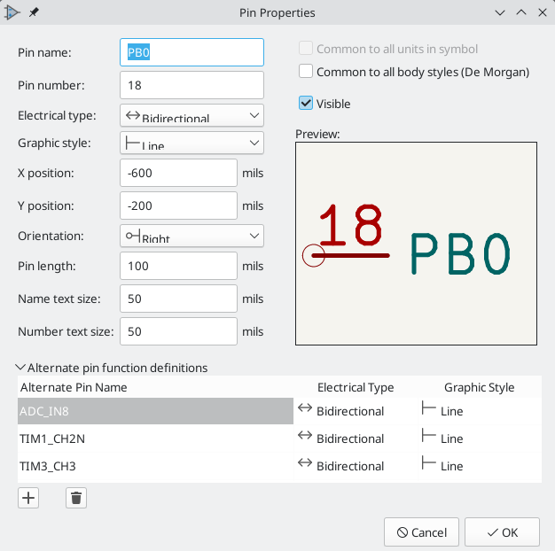
Alternate pin functions are selected in the Schematic Editor once the symbol has been placed in the schematic. For information on using alternate pin functions in the schematic, see the schematic editor symbol documentation.
创建电源符号
Power symbols are symbols that are used to label a wire as part of a global power net, like VCC or GND. The power symbol’s Value field determines the net label. The behavior of power symbols is described in the electrical connections section. Power symbols are handled and created the same way as normal symbols, but there are several additional considerations described below.
将电源符号放在一个专门的库中可能是有用的。KiCad 的符号库将电源符号放在 power 库中,用户可以创建库来存储自己的电源符号。如果在符号的属性中勾选了 定义为电源符号 框,该符号就会出现在原理图编辑器的 添加电源符号 对话框中,以便于访问。
Power symbols consist of a single pin of type Power Input. They must also have the Define as power symbol property checked.
In previous versions of KiCad, a power symbol’s pin needed to be both a
power input pin and invisible, and the pin’s name determined the name of
the net that the power symbol connected with. Beginning in KiCad version
8, the pin in a power symbol does not need to be invisible, and the net is
determined by the power symbol’s Value field.
|
下面是一个 GND 电源符号的例子。
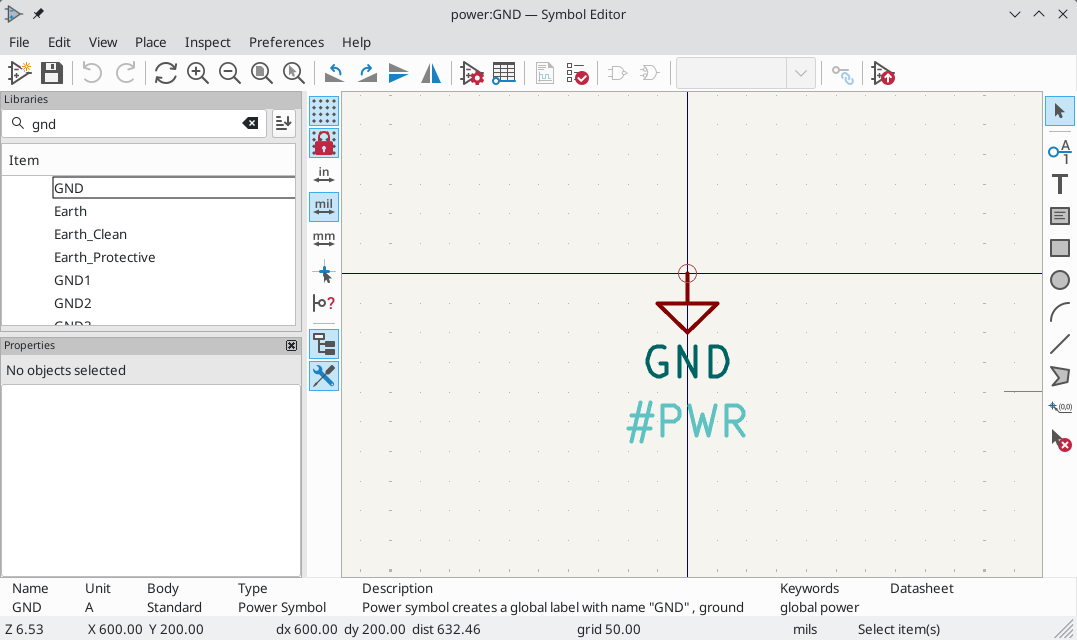
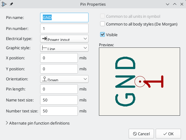
要创建一个电源符号,请使用以下步骤:
-
Add a pin of type Power input. Make the pin number
1, the length0, set the graphic style to Line, and make the pin visible. The pin number, name, length, and line style do not matter electrically. -
Place the pin on the symbol anchor. This is not required but makes it easier to place the power symbol in the schematic.
-
使用形状工具来绘制符号图形。
-
Set the symbol value to the desired net name. The symbol value is electrically important: it determines the symbol’s connected net name. This field can be changed later, after the symbol has been placed in the schematic, which will change which net the symbol connects to.
-
Check the Define as power symbol box in Symbol Properties window. This makes the symbol appear in the Add Power Symbol dialog, prevents the symbol from being assigned a footprint, and excludes the symbol from the board, BOM, and netlists.
-
Also deselect the Show pin number and Show pin name options in the Symbol Properties window. This is not necessary but improves the symbol’s appearance.
-
设置符号的位号并取消勾选 显示 框。位号第一个字符应为
#,后续文本并不重要。对于上面所示的电源符号,位号可以是#GND。位号以#开头的符号不会被添加到 PCB 上,不包括在物料清单的输出或网表中,也不会在封装分配工具中分配一个封装。如果一个电源符号的位号不是以\#开头,当运行批注或封装分配工具时,该符号会被自动插入到符号表中。
An easier method to create a new power symbol is to use another symbol as a starting point.
检查符号
符号编辑器可以检查符号中的常见问题。使用顶部工具栏上的 ![]() 按钮运行符号检查器。
按钮运行符号检查器。
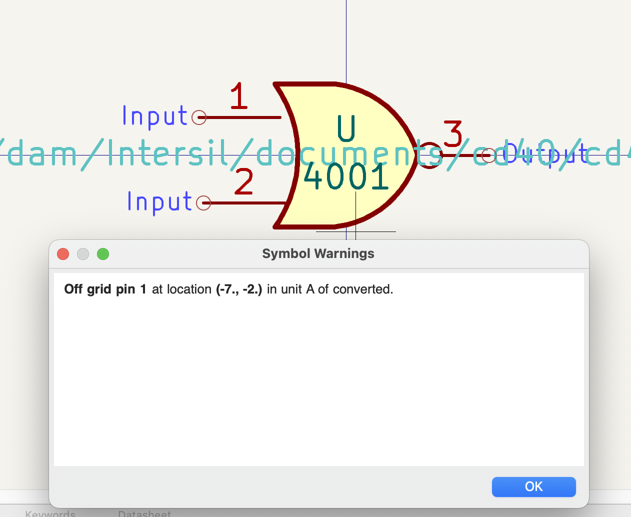
符号检查器检查的是:
-
Pins that are off-grid (pins are considered off grid if their position is not a multiple of the current symbol editor grid. It is strongly recommended to use a 50 mil grid for symbol pins)
-
Pins that are duplicated
-
Issues with graphical shapes, such as zero-sized shapes
-
非法的位号前缀:位号前缀不能用数字或
? -
设计不正确的《电源符号,电源符号》。电源符号应该有:
-
单个引脚
-
没有备用的主体样式
-
单个引脚,其类型为电源输出(见《电源标记,电源标记》),或可见且类型为电源输入(见《电源符号,电源符号》)。
-
-
在非电源符号中,出现了《隐藏的电源输入引脚,隐藏的电源输入引脚》:这将产生隐形的连接,不推荐使用
| In previous versions of KiCad, power symbols required an invisible power input pin so that they would make a global connection. In KiCad 8, the power input pin does not need to be invisible. Therefore the symbol checker will report if invisible power input pins are detected. |
浏览符号库
The Symbol Library Browser allows you to quickly examine the contents of symbol libraries. The Symbol Library Viewer can be accessed by clicking ![]() icon on the main Symbol Editor toolbar or with View → Symbol Library Browser.
icon on the main Symbol Editor toolbar or with View → Symbol Library Browser.
To examine the contents of a library, select a library from the list in the left hand panel. All symbols in the selected library will appear in the second panel. Select a symbol name to view the symbol.
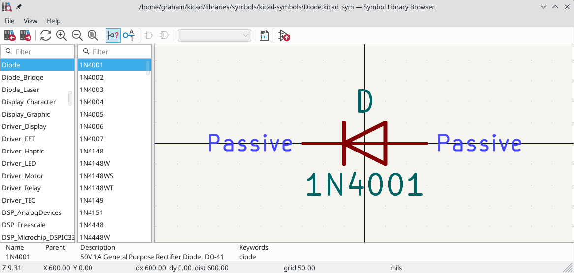
双击符号名称或使用 ![]() 按钮将符号添加到原理图中。
按钮将符号添加到原理图中。
顶部的工具条包含以下命令:
|
Select previous symbol in library. |
|
Select next symbol in library. |
|
Zoom tools. |
|
Toggle display of pin electrical types. |
|
Toggle display of pin numbers. |
|
Select standard or alternate De Morgan representation of symbol, if applicable. |
|
Select the unit of a multi-unit symbol. |
|
Open the symbol’s datasheet, if it is defined. |
|
Insert current symbol into the schematic. |