参考手册
版权
This document is Copyright © 2024 by its contributors as listed below. You may distribute it and/or modify it under the terms of either the GNU General Public License (http://www.gnu.org/licenses/gpl.html), version 3 or later, or the Creative Commons Attribution License (http://creativecommons.org/licenses/by/3.0/), version 3.0 or later.
贡献者
Jean-Pierre Charras, Graham Keeth
翻译人员
taotieren <[email protected]>, 2019-2023.
Telegram 简体中文交流群: https://t.me/KiCad_zh_CN
反馈
The KiCad project welcomes feedback, bug reports, and suggestions related to the software or its documentation. For more information on how to submit feedback or report an issue, please see the instructions at https://www.kicad.org/help/report-an-issue/
Introduction to the KiCad Drawing Sheet Editor
The Drawing Sheet Editor is a tool to create custom drawing sheets for use in the KiCad Schematic and Board Editors. Drawing sheets can include custom title blocks, frames, logos, as well as other text and graphics.
The frame, title block, and other graphic items (logos) are collectively called a drawing sheet.
Basic drawing sheet items are:
-
直线
-
矩形
-
Text (with keywords that will be replaced by the actual text, like the date, page number…) in the Schematic or Board Editors.
-
多边形 (主要用于放置 LOGO 和特殊图形形状)
-
位图 。
| 位图只能由少量绘图仪绘制(仅限 PDF 和 PS)因此,对于其他绘图仪,仅绘制边界框。 |
-
Items can be repeated, and text and poly_polygons can be rotated.
Drawing Sheet Editor files
The Drawing Sheet Editor reads and writes KiCad drawing sheet files (.kicad_wks). These files can be used as custom drawing sheets for schematic and PCB designs by selecting a custom drawing sheet in the Page Setup dialog in each editor.
When the Drawing Sheet Editor is first opened, it displays the default KiCad drawing sheet is used until a different drawing sheet file is opened.
运作理论
Basic drawing sheet item properties
Basic drawing sheet items are:
-
直线
-
矩形
-
Text (with keywords, with will be replaced by the actual text, like the date, page number…) in the Schematic or PCB Editors.
-
Poly-polygons (mainly to place logos and special graphic shapes). These poly polygons are created by the Image Converter tool, and cannot be built inside the Drawing Sheet Editor, because it is not possible to create such shapes by hand.
-
位图 用于放置 LOGO。
| 位图只能由少量绘图仪绘制:仅限 PDF 和 PS。 |
因此:
-
Text, poly-polygons and bitmaps are defined by a position, and can be rotated.
-
线 (实际上是段)和 矩形 由两点定义: 起点和终点。 它们不能旋转(这是没用的 对于线)。
这些基本项目可以重复。
Repeated text also accepts an increment value for labels (has meaning only if the text is one letter or one digit).
坐标定义
Each position, start point and end point of items is always relative to a page corner. This feature allows you to define a drawing sheet which is not dependent on the paper size.
参考角和坐标:
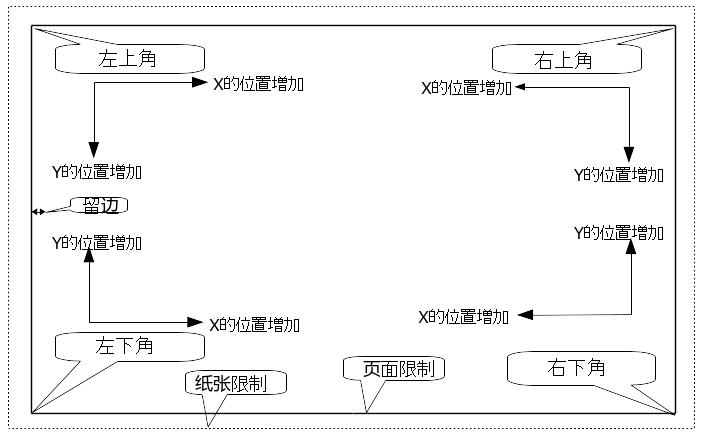
-
更改页面大小时,项目相对于其参考角的位置不会更改。
-
通常,标题栏附加到右下角,因此在创建项目时,此角是默认角。
对于具有两个定义点的矩形和线段,每个点都有其参考角。
旋转
Items which have a position defined by just one point (text and poly-polygons) can be rotated:
正常:旋转 = 0
旋转:旋转 = 20 和 10 度。
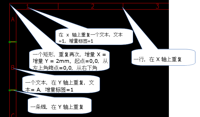
重复选项
项目可以重复:
这对于创建网格和网格标签很有用。
Text and keywords
Keywords
Text can be simple strings or can include keywords.
Keywords are replaced by actual values when the drawing sheet is used in a schematic or PCB design. They behave like text variables in the Schematic and Board Editors, except the values are either automatically set by the editor or set by the user in the Page Setup dialog of the respective editor.
The keyword syntax is ${KEYWORD}. The keyword, including the surrounding ${}, will be replaced by the keyword’s value.
| Keyword name | Description |
|---|---|
|
Version number of KiCad. |
|
Sheet number. |
|
Total number of sheets. |
|
Contents of the |
|
Contents of the |
|
Filename of the schematic or PCB design file, with a file extension. |
|
Contents of the |
|
Name of the current PCB layer. This is blank in the Schematic and Board Editors. It is only shown in plots of PCB designs. |
|
Current sheet’s paper size, which is set in Page Setup. |
|
Contents of the |
|
Sheet name of the current sheet. This is blank in the Board Editor. |
|
Sheet path of the current sheet. This is blank in the Board Editor. |
|
Contents of the |
For example, Size: ${PAPER} displays "Size: A4" when the paper size is set to A4.
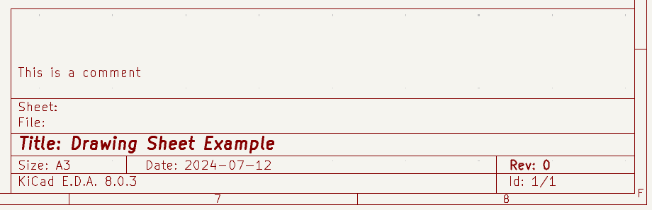
When the Preview display mode is active (![]() ), the title block is displayed like in the Schematic and PCB Editors, with keywords replaced with the corresponding values. You can configure the displayed values in the Page Preview Settings dialog (
), the title block is displayed like in the Schematic and PCB Editors, with keywords replaced with the corresponding values. You can configure the displayed values in the Page Preview Settings dialog (![]() ).
).
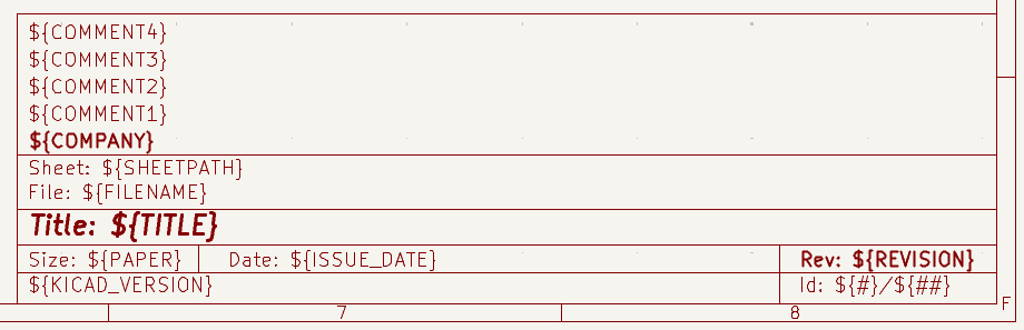
When the Edit mode is active (![]() ), the title block is displayed without replacing keywords.
), the title block is displayed without replacing keywords.
Multi-line text
Text can be multi-line.
There are 2 ways to insert a new line in text:
-
Insert the
\n2 chars sequence (mainly in Page setup dialog in KiCad). -
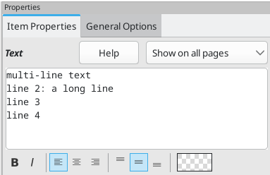
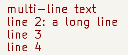
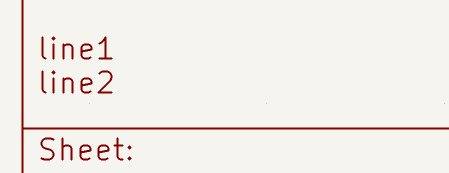
Insert a new line in the Drawing Sheet Editor Design window.
这是一个例子:
设置
输出
Multi-line text in Page Setup dialog
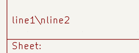
In the Page Setup dialog, text controls do not accept multi-line text.
The \n 2 character sequence should be inserted to force a new line inside a text object.
Here is a two line text object, in the Comment2 field:

这是实际的文字:
However, if you really want the \n inside the text, enter \\n.

并显示的文字:
约束
第 1 页约束
When using the Schematic Editor, the full schematic often uses more than one page.
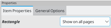
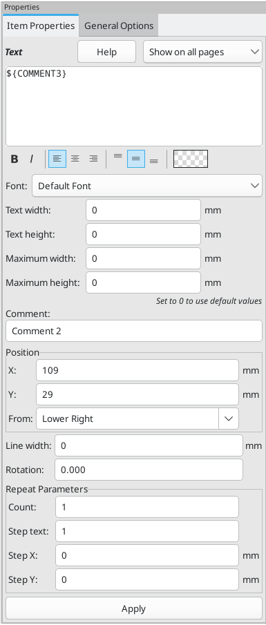
Usually drawing sheet items are shown on all pages, but you can also set each item to be shown only on the first page or on all pages except the first page. To change which pages an item is shown on, use the dropdown in the the item’s Item Properties panel. Options are show on all pages, first page only, and subsequent pages only.
Text maximum size constraint
Text items have a maximum size constraint. You can set a maximum height and maximum width, which together form a bounding box defining the maximum size of the text object.
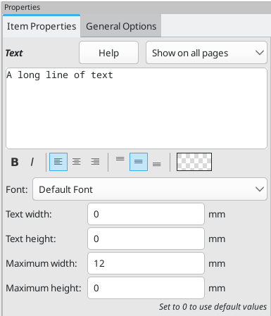
If the text object is bigger than the maximum size in a given dimension, the text object will be dynamically compressed in that dimension in order to fit within the bounding box. This will result in the text being visually distorted. If the text fits within the bounding box, the text will not be compressed.
When either parameter is set to 0, KiCad will not enforce a maximum size in that dimension.
Some text with the maximum height and width set to 0:
The same text compressed because the maximum width is set smaller than the width of the text:

Invoking the Drawing Sheet Editor
The Drawing Sheet Editor is typically invoked from a command line, or from the KiCad Project Manager.
从命令行,语法是 pl_editor <*.kicad_wks 文件打开>。
Drawing Sheet Editor Commands
主屏幕
The image below shows the main window of the Drawing Sheet Editor.
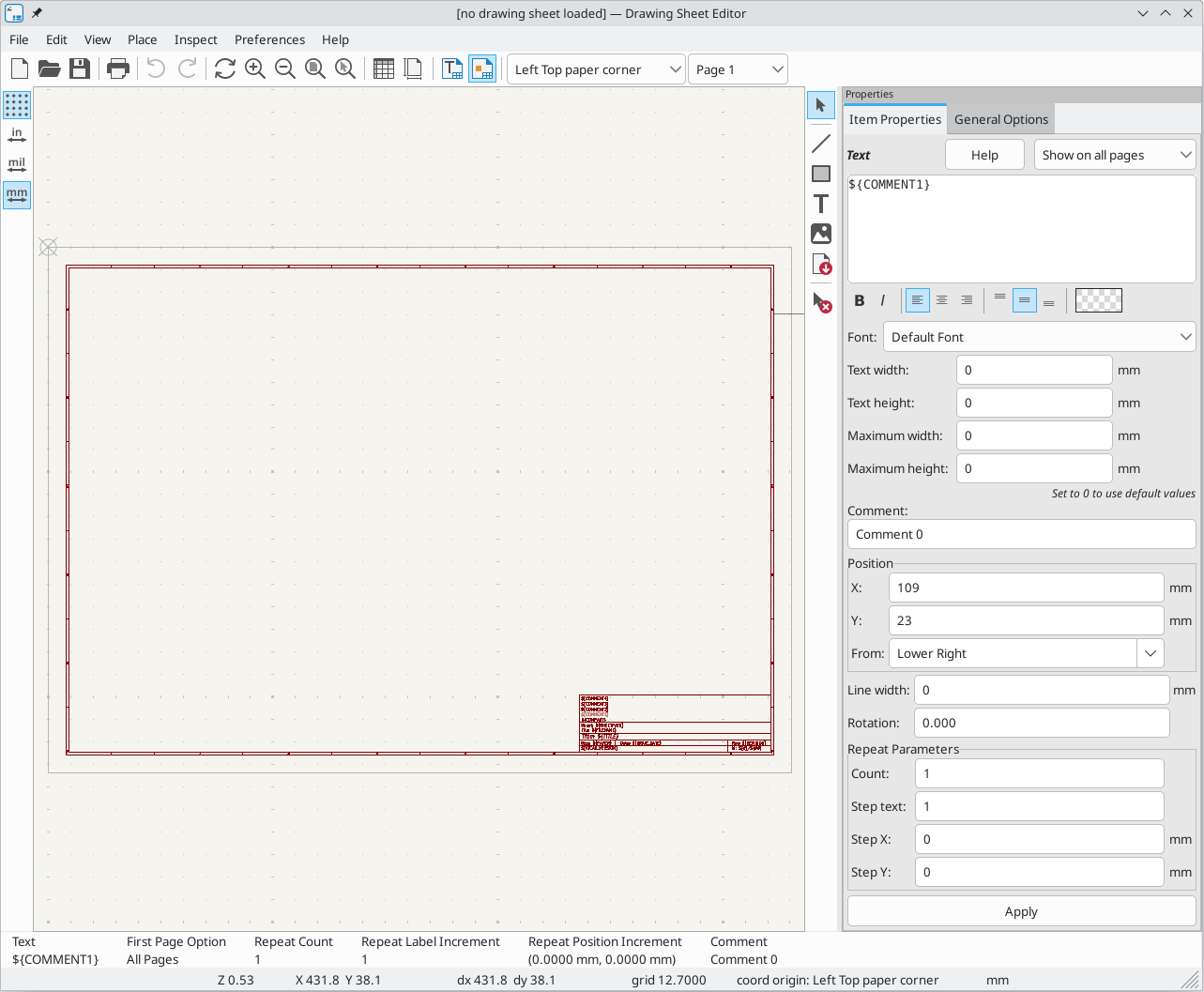
The main part of the screen is the editing canvas for the open drawing sheet.
The right pane is a properties editor for editing the selected item. It only appears when an item is selected in the canvas.
主窗口工具栏
顶部工具栏可以轻松访问以下命令:
|
Create a new drawing sheet. |
|
Load a drawing sheet file. |
|
Save the current drawing sheet in a |
|
Display the page size selector and the title block user data editor. |
|
Prints the current page. |
|
Undo/redo tools. |
|
Zoom in, out, redraw and auto, respectively. |
|
Show the drawing sheet in Preview mode: text is shown like in the Schematic or PCB Editors, with text keywords replaced by user text. |
|
Show the drawing sheet in Edit mode: text is displayed "as is", without any keyword replacement. |
|
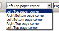
Reference corner selection, for coordinates displayed to the status bar. |
|
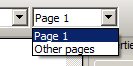
Selection of the page number (page & or other pages). This selection has meaning only if some items than have a page option, are not shown on all pages (in a schematic for instance, which contains more than one page). |
绘图区域中的命令(绘图面板)
键盘命令
F1 |
放大 |
F2 |
缩小 |
F3 |
刷新显示 |
F4 |
将光标移动到显示窗口的中心 |
Home |
将封装放入显示窗口 |
空格键 |
设置当前光标位置的相对坐标 |
右箭头 |
将光标向右移动一个网格位置 |
向左箭头 |
将光标向左移动一个网格位置 |
向上箭头 |
将光标向上移动一个网格位置 |
向下箭头 |
将光标向下移动一个网格位置 |
鼠标命令
滚轮 |
在当前光标位置放大和缩小 |
Ctrl +滚轮 |
左右平移 |
Shift +滚轮 |
上下平移 |
右键单击 |
打开上下文菜单 |
上下文菜单
通过右键单击鼠标显示:
-
添加线
-
添加矩形
-
添加文字
-
Add Bitmap
-
缩放选择:直接选择显示缩放。
-
网格选择:直接选择网格。
状态栏信息
The status bar is located at the bottom of the Drawing Sheet Editor and provides useful information to the user.

Coordinates are always relative to the corner selected as the reference corner in the reference corner dropdown in the menubar.
Properties editor
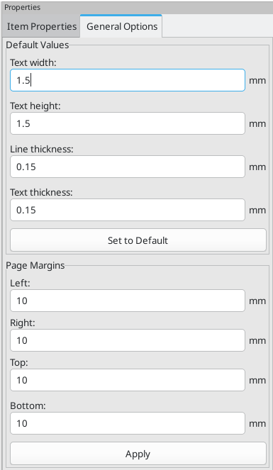
The right pane is a properties editor. It only appears when an item is selected in the canvas. The Item Properties tab contains properties for the selected item. These properties depend on what type of item is selected. The General Options tab lets you edit default properties and margins for the *sheet.
Changes made in the properties editor are not applied until you click the Apply button.
|
|
Design Inspector window
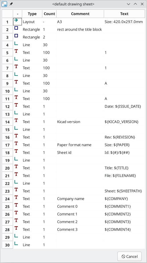
The Design Inspector shows a table of every item in the drawing sheet and their properties. Selecting an item in the Design Inspector also selects the item on the canvas and leaves it selected when you close the Design Inspector.
To open the Design Inspector, use Inspect → Show Design Inspector.
Interactive editing
项目选择
可以选择一个项目:
-
From the Design Inspector
-
通过左键单击它。
-
通过右键单击它(将显示一个弹出菜单)。
When selected, this item is drawn in a lighter shade of color and the properties editor will be displayed for the selected item.
When right clicking on the item, a pop-up menu is displayed. The pop menu contents depend on the type of object selected.
项目创建
To add a new item, use the appropriate button in the right toolbar and then click on the canvas. The item will be added to the canvas and selected, and the properties editor for the new item will open. You can edit the item’s properties in the properties editor, then click Apply to modify the new item.
The available items are lines (![]() ), rectangles (
), rectangles (![]() ), text (
), text (![]() ), and bitmaps (
), and bitmaps (![]() ).
).
You can also add new items from the right-click context menu.
Logos must first be created by the Image Converter tool, which creates a page layout description file. You can use the Append Existing Drawing Sheet command to insert the logo (a poly polygon) contained in the new drawing sheet.
Adding lines, rectangles and text
When you add lines, rectangles, or text, the item will be added to the canvas, selected, and shown in the properties editor. You can edit the item’s properties in the properties editor, then click Apply to apply the changes.
You can also move the item in the canvas after it has been placed by dragging it or using the Move command (kbd:[M]). Lines and rectangles can be moved as a shape, but you can also move their points individually.
Lines and rectangles typically use the same corner reference for both the start and end points. If this is not the case, the item’s geometry will change when the sheet size or margins are changed.
添加 LOGO
To add a logo, a poly polygon (the vectored image of the logo) must be first created using the Image Converter tool, which is available in the main KiCad Project Manager window. Polygons cannot be created by hand.
The Image Converter tool creates a drawing sheet file which contains only one item: a poly polygon representing the source image. This drawing sheet file is appended to the current design, using the Append Existing Drawing Sheet command.
| This command can be used to append any drawing sheet file, regardless of what items it contains. All items in the appended file will be added to the current design. |
插入多边形后,可以移动它并编辑其参数。
添加图像位图
You can add an image bitmap using many common bitmap formats (PNG, JPEG, BMP, etc.).
-
导入位图时,其 PPI(每英寸像素数)定义设置为 300PPI。
-
This value can be modified in the properties editor.
-
The actual size of the bitmap in the drawing sheet depends on this parameter.
-
Be aware that using higher definition values brings larger output files, and can have an effect on draw or plot time.
Bitmaps can be repeated but not rotated.