Manuel de référence
Copyright
This document is Copyright © 2024 by its contributors as listed below. You may distribute it and/or modify it under the terms of either the GNU General Public License (http://www.gnu.org/licenses/gpl.html), version 3 or later, or the Creative Commons Attribution License (http://creativecommons.org/licenses/by/3.0/), version 3.0 or later.
Contributeurs
Jean-Pierre Charras, Graham Keeth
Traduction
Marc Berlioux <[email protected]>, 2015-2016.
Retours
The KiCad project welcomes feedback, bug reports, and suggestions related to the software or its documentation. For more information on how to submit feedback or report an issue, please see the instructions at https://www.kicad.org/help/report-an-issue/
Introduction to the KiCad Drawing Sheet Editor
The Drawing Sheet Editor is a tool to create custom drawing sheets for use in the KiCad Schematic and Board Editors. Drawing sheets can include custom title blocks, frames, logos, as well as other text and graphics.
The frame, title block, and other graphic items (logos) are collectively called a drawing sheet.
Basic drawing sheet items are:
-
Des Lignes.
-
Des Rectangles.
-
Text (with keywords that will be replaced by the actual text, like the date, page number…) in the Schematic or Board Editors.
-
Des Poly-polygones (principalement pour insérer des logos et des formes graphiques spéciales).
-
Des Images Bitmaps.
| Les images Bitmaps n’apparaîtront que dans certains tracés (PDF et PS seulement). Par conséquent, pour les autres tracés, seule une boite de délimitation sera tracée. |
-
Items can be repeated, and text and poly_polygons can be rotated.
Drawing Sheet Editor files
The Drawing Sheet Editor reads and writes KiCad drawing sheet files (.kicad_wks). These files can be used as custom drawing sheets for schematic and PCB designs by selecting a custom drawing sheet in the Page Setup dialog in each editor.
When the Drawing Sheet Editor is first opened, it displays the default KiCad drawing sheet is used until a different drawing sheet file is opened.
Théorie des opérations
Basic drawing sheet item properties
Basic drawing sheet items are:
-
Des Lignes.
-
Des Rectangles.
-
Text (with keywords, with will be replaced by the actual text, like the date, page number…) in the Schematic or PCB Editors.
-
Poly-polygons (mainly to place logos and special graphic shapes). These poly polygons are created by the Image Converter tool, and cannot be built inside the Drawing Sheet Editor, because it is not possible to create such shapes by hand.
-
Des Bitmaps pour insérer des logos.
| Les images Bitmaps n’apparaîtront que dans certains tracés (PDF et PS seulement). |
Par conséquent :
-
Text, poly-polygons and bitmaps are defined by a position, and can be rotated.
-
Les Lignes (les segments, en fait) et les rectangles sont définis par deux points : un point de début et un point de fin. Ils ne peuvent pas être tournés (c’est inutile pour les segments).
Ces éléments de base peuvent être répétés.
Repeated text also accepts an increment value for labels (has meaning only if the text is one letter or one digit).
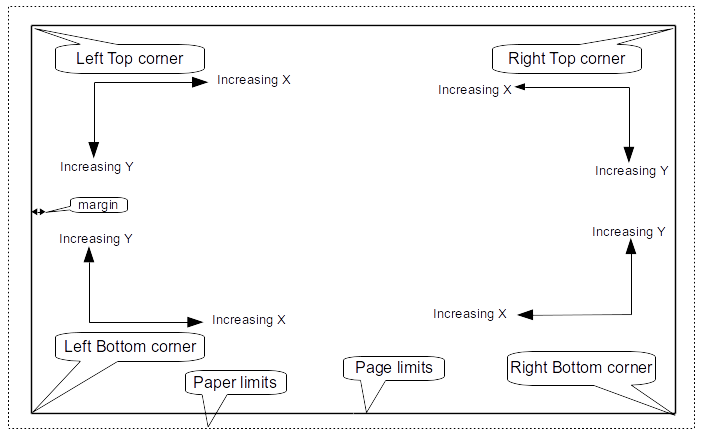
Définition des coordonnées
Each position, start point and end point of items is always relative to a page corner. This feature allows you to define a drawing sheet which is not dependent on the paper size.
Référence des coins et coordonnées :
-
Lorsque la taille de la page est modifiée, la position de l’élément par rapport à son coin de référence ne change pas.
-
Habituellement, les blocs de titre sont attachés au coin inférieur droit. Par conséquent ce coin est le coin par défaut lors de la création d’un élément.
Pour les rectangles et les segments, qui sont définis par deux points, chaque point a son coin de référence.
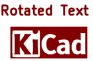
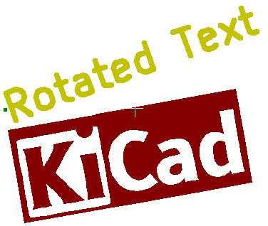
Rotation
Items which have a position defined by just one point (text and poly-polygons) can be rotated:
Normal : Rotation = 0
Tourné : Rotation = 20 et 10 degrés.
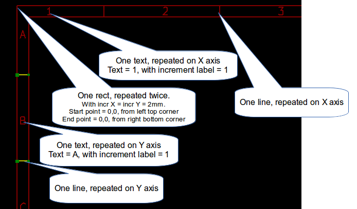
Option de Répétition
Les éléments peuvent être répétés :
Ceci est utile pour créer des grilles et des étiquettes de grilles.
Text and keywords
Keywords
Text can be simple strings or can include keywords.
Keywords are replaced by actual values when the drawing sheet is used in a schematic or PCB design. They behave like text variables in the Schematic and Board Editors, except the values are either automatically set by the editor or set by the user in the Page Setup dialog of the respective editor.
The keyword syntax is ${KEYWORD}. The keyword, including the surrounding ${}, will be replaced by the keyword’s value.
| Keyword name | Description |
|---|---|
|
Version number of KiCad. |
|
Sheet number. |
|
Total number of sheets. |
|
Contents of the |
|
Contents of the |
|
Filename of the schematic or PCB design file, with a file extension. |
|
Contents of the |
|
Name of the current PCB layer. This is blank in the Schematic and Board Editors. It is only shown in plots of PCB designs. |
|
Current sheet’s paper size, which is set in Page Setup. |
|
Contents of the |
|
Sheet name of the current sheet. This is blank in the Board Editor. |
|
Sheet path of the current sheet. This is blank in the Board Editor. |
|
Contents of the |
For example, Size: ${PAPER} displays "Size: A4" when the paper size is set to A4.
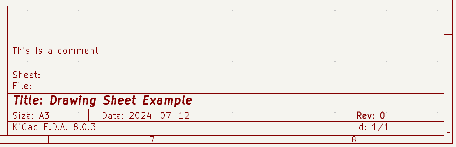
When the Preview display mode is active (![]() ), the title block is displayed like in the Schematic and PCB Editors, with keywords replaced with the corresponding values. You can configure the displayed values in the Page Preview Settings dialog (
), the title block is displayed like in the Schematic and PCB Editors, with keywords replaced with the corresponding values. You can configure the displayed values in the Page Preview Settings dialog (![]() ).
).
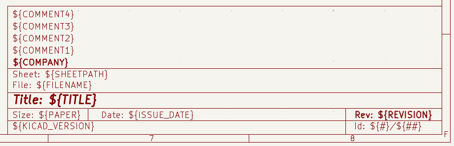
When the Edit mode is active (![]() ), the title block is displayed without replacing keywords.
), the title block is displayed without replacing keywords.
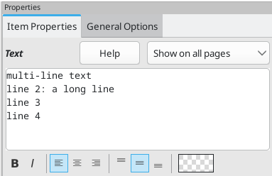
Multi-line text
Text can be multi-line.
There are 2 ways to insert a new line in text:
-
Insert the
\n2 chars sequence (mainly in Page setup dialog in KiCad). -
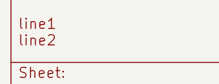
Insert a new line in the Drawing Sheet Editor Design window.
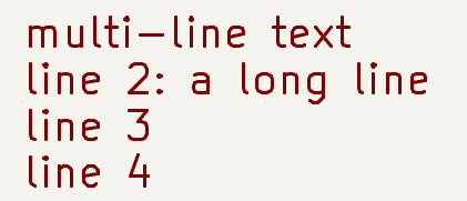
Voici un exemple :
Réglages
Sortie
Multi-line text in Page Setup dialog
In the Page Setup dialog, text controls do not accept multi-line text.
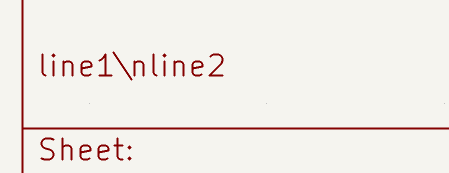
The \n 2 character sequence should be inserted to force a new line inside a text object.
Here is a two line text object, in the Comment2 field:

Voici le texte réel affiché :
However, if you really want the \n inside the text, enter \\n.

Le texte affiché :
Constraints
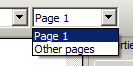
Page 1 constraint
When using the Schematic Editor, the full schematic often uses more than one page.
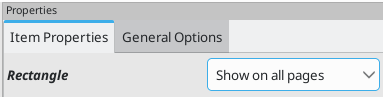
Usually drawing sheet items are shown on all pages, but you can also set each item to be shown only on the first page or on all pages except the first page. To change which pages an item is shown on, use the dropdown in the the item’s Item Properties panel. Options are show on all pages, first page only, and subsequent pages only.
Text maximum size constraint
Text items have a maximum size constraint. You can set a maximum height and maximum width, which together form a bounding box defining the maximum size of the text object.
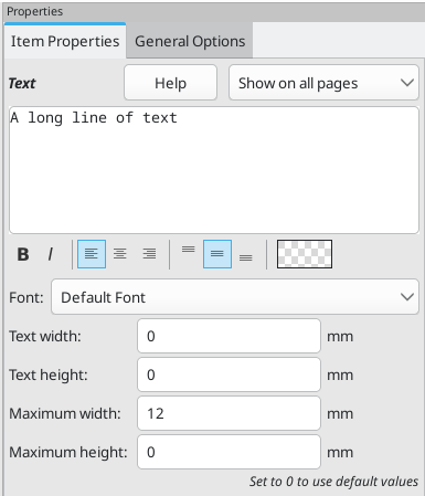
If the text object is bigger than the maximum size in a given dimension, the text object will be dynamically compressed in that dimension in order to fit within the bounding box. This will result in the text being visually distorted. If the text fits within the bounding box, the text will not be compressed.
When either parameter is set to 0, KiCad will not enforce a maximum size in that dimension.
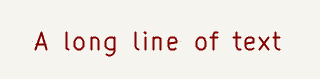
Some text with the maximum height and width set to 0:
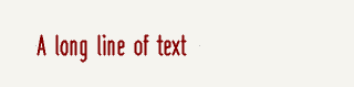
The same text compressed because the maximum width is set smaller than the width of the text:
Invoking the Drawing Sheet Editor
The Drawing Sheet Editor is typically invoked from a command line, or from the KiCad Project Manager.
From a command line, the syntax is pl_editor <*.kicad_wks file to open>.
Drawing Sheet Editor Commands
Main Screen
The image below shows the main window of the Drawing Sheet Editor.
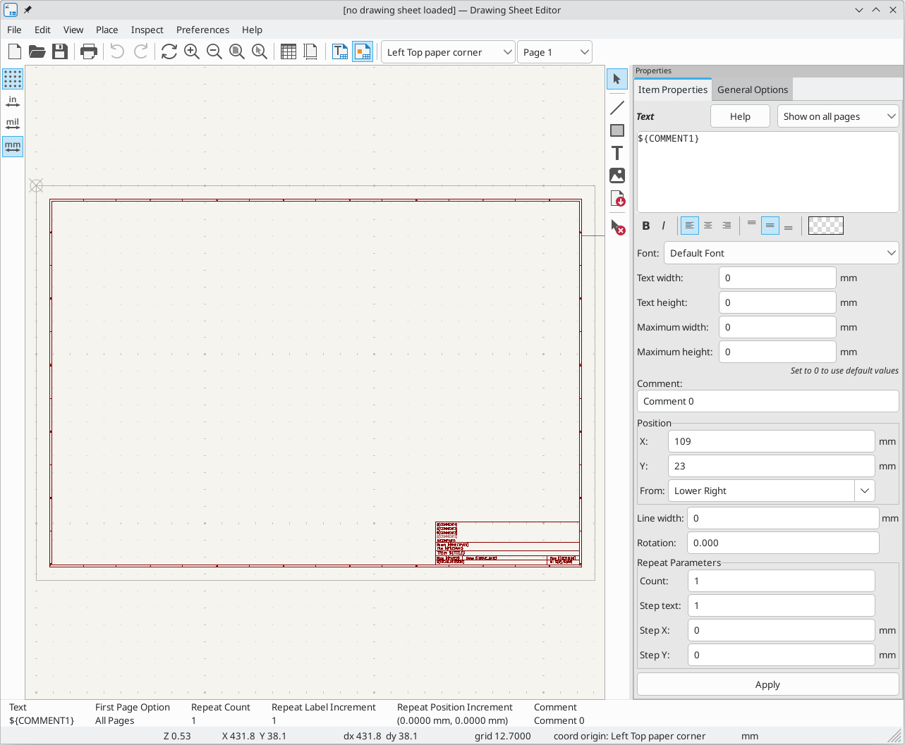
The main part of the screen is the editing canvas for the open drawing sheet.
The right pane is a properties editor for editing the selected item. It only appears when an item is selected in the canvas.
Main Window Toolbar
The top toolbar allows for easy access to the following commands:
|
Create a new drawing sheet. |
|
Load a drawing sheet file. |
|
Save the current drawing sheet in a |
|
Display the page size selector and the title block user data editor. |
|
Prints the current page. |
|
Undo/redo tools. |
|
Zoom in, out, redraw and auto, respectively. |
|
Show the drawing sheet in Preview mode: text is shown like in the Schematic or PCB Editors, with text keywords replaced by user text. |
|
Show the drawing sheet in Edit mode: text is displayed "as is", without any keyword replacement. |
|
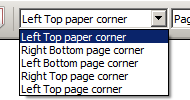
Reference corner selection, for coordinates displayed to the status bar. |
|
Selection of the page number (page & or other pages). This selection has meaning only if some items than have a page option, are not shown on all pages (in a schematic for instance, which contains more than one page). |
Commands in drawing area (draw panel)
Keyboard Commands
F1 |
Zoom In |
F2 |
Zoom Out |
F3 |
Refresh Display |
F4 |
Move cursor to center of display window |
Home |
Fit footprint into display window |
Space Bar |
Set relative coordinates to the current cursor position |
Right Arrow |
Move cursor right one grid position |
Left Arrow |
Move cursor left one grid position |
Up Arrow |
Move cursor up one grid position |
Down Arrow |
Move cursor down one grid position |
Mouse Commands
Scroll Wheel |
Zoom in and out at the current cursor position |
Ctrl + Scroll Wheel |
Pan right and left |
Shift + Scroll Wheel |
Pan up and down |
Right Button Click |
Open context menu |
Context Menu
Displayed by right-clicking the mouse:
-
Add Line
-
Add Rectangle
-
Add Text
-
Add Bitmap
-
Zoom selection: direct selection of the display zoom.
-
Grid selection: direct selection of the grid.
Status Bar Information
The status bar is located at the bottom of the Drawing Sheet Editor and provides useful information to the user.

Coordinates are always relative to the corner selected as the reference corner in the reference corner dropdown in the menubar.
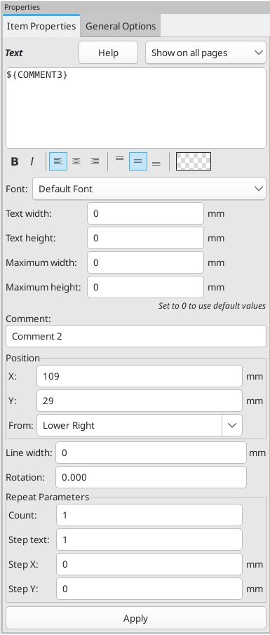
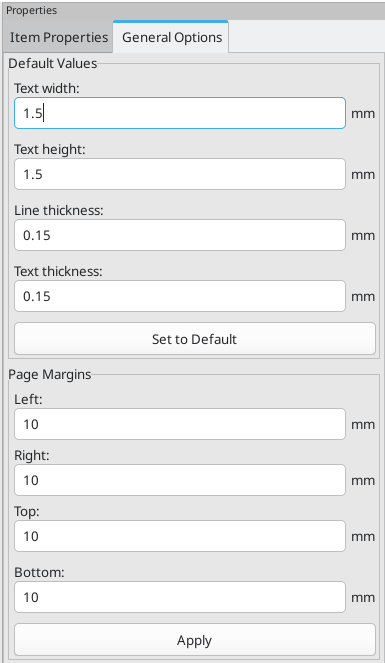
Properties editor
The right pane is a properties editor. It only appears when an item is selected in the canvas. The Item Properties tab contains properties for the selected item. These properties depend on what type of item is selected. The General Options tab lets you edit default properties and margins for the *sheet.
Changes made in the properties editor are not applied until you click the Apply button.
|
|
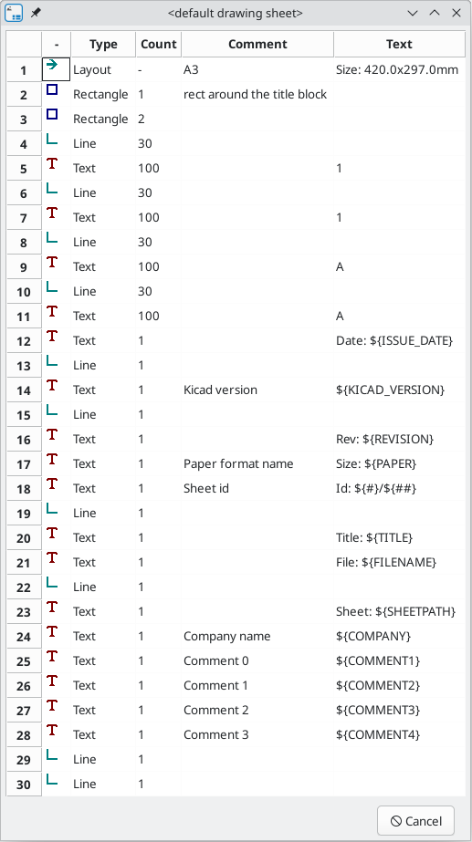
Design Inspector window
The Design Inspector shows a table of every item in the drawing sheet and their properties. Selecting an item in the Design Inspector also selects the item on the canvas and leaves it selected when you close the Design Inspector.
To open the Design Inspector, use Inspect → Show Design Inspector.
Interactive editing
Item selection
An item can be selected:
-
From the Design Inspector
-
By Left clicking on it.
-
By Right clicking on it (and a pop up menu will be displayed).
When selected, this item is drawn in a lighter shade of color and the properties editor will be displayed for the selected item.
When right clicking on the item, a pop-up menu is displayed. The pop menu contents depend on the type of object selected.
Item creation
To add a new item, use the appropriate button in the right toolbar and then click on the canvas. The item will be added to the canvas and selected, and the properties editor for the new item will open. You can edit the item’s properties in the properties editor, then click Apply to modify the new item.
The available items are lines (![]() ), rectangles (
), rectangles (![]() ), text (
), text (![]() ), and bitmaps (
), and bitmaps (![]() ).
).
You can also add new items from the right-click context menu.
Logos must first be created by the Image Converter tool, which creates a page layout description file. You can use the Append Existing Drawing Sheet command to insert the logo (a poly polygon) contained in the new drawing sheet.
Adding lines, rectangles and text
When you add lines, rectangles, or text, the item will be added to the canvas, selected, and shown in the properties editor. You can edit the item’s properties in the properties editor, then click Apply to apply the changes.
You can also move the item in the canvas after it has been placed by dragging it or using the Move command (kbd:[M]). Lines and rectangles can be moved as a shape, but you can also move their points individually.
Lines and rectangles typically use the same corner reference for both the start and end points. If this is not the case, the item’s geometry will change when the sheet size or margins are changed.
Adding logos
To add a logo, a poly polygon (the vectored image of the logo) must be first created using the Image Converter tool, which is available in the main KiCad Project Manager window. Polygons cannot be created by hand.
The Image Converter tool creates a drawing sheet file which contains only one item: a poly polygon representing the source image. This drawing sheet file is appended to the current design, using the Append Existing Drawing Sheet command.
| This command can be used to append any drawing sheet file, regardless of what items it contains. All items in the appended file will be added to the current design. |
Once a poly polygon is inserted, it can be moved and its parameters edited.
Adding image bitmaps
You can add an image bitmap using many common bitmap formats (PNG, JPEG, BMP, etc.).
-
When a bitmap is imported, its PPI (pixel per inch) definition is set to 300PPI.
-
This value can be modified in the properties editor.
-
The actual size of the bitmap in the drawing sheet depends on this parameter.
-
Be aware that using higher definition values brings larger output files, and can have an effect on draw or plot time.
Bitmaps can be repeated but not rotated.