Generating Outputs
Printing
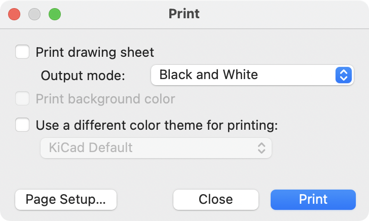
KiCad can print the schematic to a standard printer using File→Print….
Printing options
-
Print drawing sheet: Include the drawing sheet border and title block in the printed schematic.
-
Output mode: Print the schematic in color or black and white.
-
Print background color: Include the background color in the printed schematic. This option is only enabled when printing in color.
-
Use a different color theme for printing: Select a different color scheme for printing than the one selected for display in the Schematic Editor.
-
Page Setup…: Opens a page setup dialog for setting paper size and orientation.
-
Close: Closes the dialog without printing.
-
Print: Opens the system print dialog.
| Printing uses platform- and printer-specific drivers and may have unexpected results. When printing to a file, Plotting is recommended instead of Printing. |
Plotting
KiCad can plot schematics to a file using File → Plot….
The supported output formats are Postscript, PDF, SVG, and DXF.
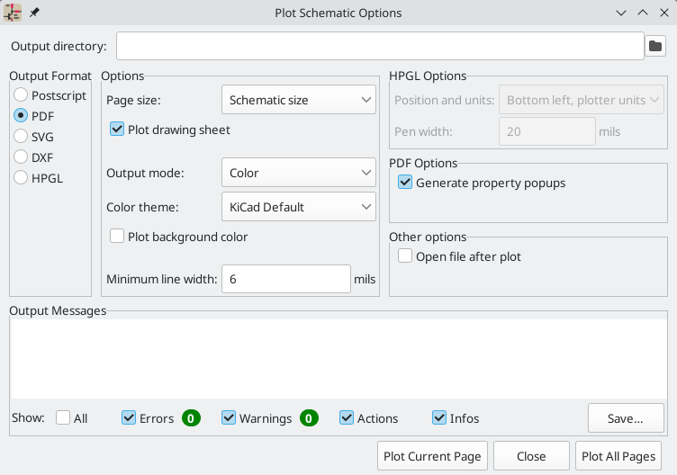
The Output Messages pane displays messages about the generated files. Different kinds of messages can be shown or hidden using the checkboxes, and the messages can be saved to a file using the Save… button.
The Plot Current Page button plots the current page of the schematic. The Plot All Pages button plots all pages of the schematic. One file is generated for each page, except for PDF output, which plots each schematic page as a separate page in a single PDF file.
Plotting options
-
Output directory: Specify the location to save plotted files. If this is a relative path, it is created relative to the project directory. This path can use text variables, including both project text variables and built-in text variables.
-
Output Format: Select the format to plot in. Some formats have different options than others.
-
Page size: Sets the page size to use for the plotted output. This can be set to match the schematic size or to another sheet size.
-
Plot drawing sheet: Include the drawing sheet border and title block in the printed schematic.
-
Output mode: Sets the output to color or black and white. Not all output formats support color.
-
Color theme: Selects the color theme to use for the plotted output.
-
Plot background color: Includes the schematic background color in the plotted output. The background color will not be plotted if the output format does not support color or the output mode is black and white.
-
Minimum line width: Selects the minimum width for lines. Any lines narrower than this width will be plotted with this minimum width.
-
Generate property popups: Enables the interactive PDF features described below. This option only applies for PDF output.
-
Generate clickable links for hierarchical elements: Enables clickable hierarchical sheets, hierarchical sheet pins, and hierarchical labels. When enabled, clicking a hierarchical sheet or sheet pin in the PDF will open the PDF page for that subsheet. Clicking a hierarchical label will open the page for the parent sheet. If Generate property popups is also enabled, links will be generated instead of property popups for hierarchical sheets, pins, and labels (i.e. this option takes priority). This option only applies for PDF output.
-
Generate metadata from AUTHOR and SUBJECT variables: Sets the Author and Subject PDF document properties for the generated PDF based on the
AUTHORandSUBJECTproject text variables, if you have defined them. This option only applies for PDF output. -
Open file after plot: automatically opens the plotted output file when plotting is complete.
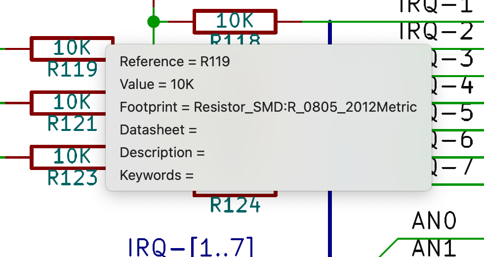
Interactive PDF features
Plotted PDFs can optionally have several interactive features.
-
Hyperlinks can be clicked.
-
The table of contents is populated with schematic sheets as well as the symbols and hierarchical labels in each sheet.
-
Clicking on many schematic elements displays a popup menu containing relevant information.
-
Symbols display their symbol fields.
-
Hierarchical subsheets display their sheetname and filename, as well as an option to enter the sheet itself. This is replaced by a direct link to the subsheet if the Generate clickable links for hierarchical elements option is enabled.
-
Labels display the resolved net and netclass.
-
Buses display their members.
-
| Some of these features are not supported in all PDF readers. The clickable links generated by the Generate clickable links for hierarchical elements option are more widely supported than other interactive features. |
Generating a bill of materials
KiCad can generate a bill of materials that lists all of the components in the design. BOMs are configurable: you can select which components are included, how components are ordered, which symbol fields are included and in what order, and what the output format is.
BOMs are exported using the Symbol Fields Table. As a
shortcut to open the Export tab of this dialog, you can select Tools →
Generate Bill of Materials… or use the
![]() button on the top toolbar.
button on the top toolbar.
The contents of the BOM are configured in the Edit tab. The format of the exported BOM file is configured in the Export tab. The BOM is written when you press the Export button at the bottom of the dialog.
BOM contents
The exported BOM will contain the components (rows) and fields (columns) shown in the Edit tab, with the same grouping and sorting.
The Exclude from BOM and Do not Populate attributes affect the Edit tab and the exported BOM as follows:
-
Components with the Exclude from BOM attribute set are always excluded from BOM exports. They are shown in the Edit tab unless the Include 'Exclude from BOM' Symbols option is unchecked in the
 menu.
menu. -
Components with the Do not Populate (DNP) attribute set are included in BOM exports and shown in the Edit tab unless the Include 'DNP' Symbols option is unchecked in the
menu.
You can filter the components that are exported by typing in the Filter textbox.
This matches against symbols' references.
Wildcards are supported:
* matches any number of any characters, including none, and ? matches any single character.
You can also limit the displayed components to those in the current sheet, the current sheet and all of its subsheets, or the entire schematic using the dropdown menu next to the filter box.
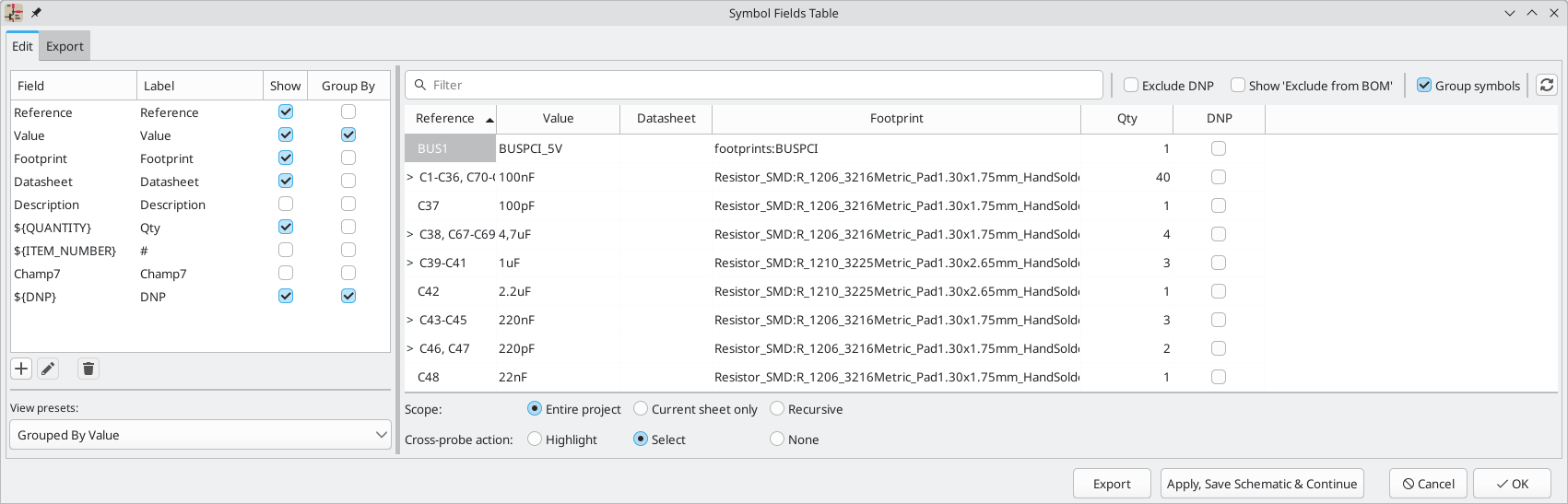
The panel on the left side of the dialog contains a list of columns
that are available to show in the Edit tab and include in the BOM.
You can collapse this panel by clicking the ![]() button.
button.
Fields with the Include box checked will be shown in the Edit tab and included as columns in the BOM. You can also show or hide columns by right clicking the column header in the right part of the dialog and selecting the desired columns. To reorder the columns, drag a column header to the left or right. You can set an arbitrary name for each column by clicking in the BOM Name column and entering a new name.
Fields with the Group By box checked are used to group components together. Components are grouped into the same line if all of their Group By fields are identical and the Group symbols box at the top of the dialog is checked.
Presets are available to configure the list of fields. Presets store which fields are displayed, which fields are used for grouping, and the column order. You can create and save your own presets or use one of several default presets. Custom presets can be deleted in this dialog or in the Schematic Setup dialog.
The built-in presets "Grouped By Value" and "Grouped By Value and Footprint" replicate legacy BOM scripts, while "Attributes" shows only the reference and value fields and the DNP, exclude from board, exclude from simulation, and exclude from BOM attributes.
Some virtual fields are available that may be useful in BOM exports. Adding a field in the Symbol Fields Table beginning with a text variable will not create a new field in the symbols, but will create a special column in the table and BOM with auto-generated values for each component. The following variables may be especially useful for creating virtual fields in custom BOM formats:
-
${QUANTITY}creates a field that contains the number of grouped instances of that component. -
${ITEM_NUMBER}creates a field that contains the row number of the component in the BOM. -
${SYMBOL_NAME}creates a field that contains the name of the schematic symbol. -
${SYMBOL_LIBRARY}creates a field that contains the name of the schematic symbol library. -
${DNP}creates a field with a checkbox that controls the component’s DNP attribute. In the BOM, this field resolves to the string "DNP" if the component’s DNP attribute is set, or an empty string otherwise. -
${EXCLUDE_FROM_BOARD}creates a field with a checkbox that controls the component’s exclude from board attribute. In the BOM, this field resolves to the string "Excluded from board" if the component’s exclude from board attribute is set, or an empty string otherwise. -
${EXCLUDE_FROM_SIM}creates a field with a checkbox that controls the component’s exclude from simulation attribute. In the BOM, this field resolves to the string "Excluded from simulation" if the component’s exclude from simulation attribute is set, or an empty string otherwise. -
${EXCLUDE_FROM_BOM}creates a field with a checkbox that controls the component’s exclude from BOM attribute. Components with the exclude from BOM attribute set are not included in the BOM.
Other text variables are also available.
The full functionality of the Edit tab, including virtual field behavior, is explained in more detail in the Symbol Fields Table documentation.
BOM format
The Export tab contains settings concerning the output file format for the BOM and displays a preview of the raw BOM file output.
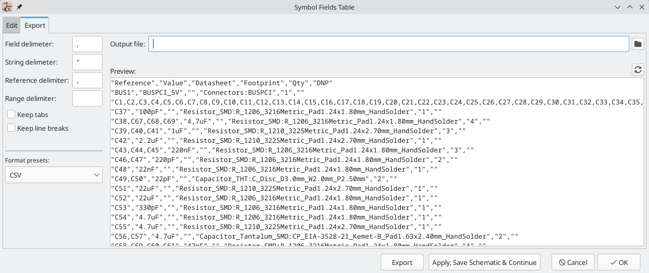
At the top you can specify the output file. Pressing the Export button will write the BOM to this file path. This path can contain text variables.
The settings on the left control how the BOM information is formatted in the
file. You can change the delimiter between fields, the delimiter that surrounds
each field, the delimiter that separates a sequence of references (e.g. the
comma in R1,R3), and the delimiter for a range of references (e.g. the dash in
R1-R3). If no range delimiter is given, ranges will not be used: R1-R3 will
be written out as R1,R2,R3, for example, assuming , as a reference
delimiter. Tabs and newlines in fields can be preserved or stripped, depending
on the Keep tabs and Keep line breaks settings.
Several default format presets are available. You can select a comma-separated value (CSV) format, a tab-separated value (TSV) format, or a semicolon-separated format. You can also create and save your own presets. Custom presets can be deleted in this dialog or in the Schematic Setup dialog.
Legacy BOM generation
Previous versions of KiCad used external scripts to process the design information into the desired output format. This BOM generation tool is still available by selecting Tools → Generate Legacy Bill of Materials….
Several BOM generator scripts are included with KiCad, and users can also create their own. BOM generator scripts generally use Python or XSLT, but other tools can be used as long as you can specify a command line for KiCad to execute when running the generator.
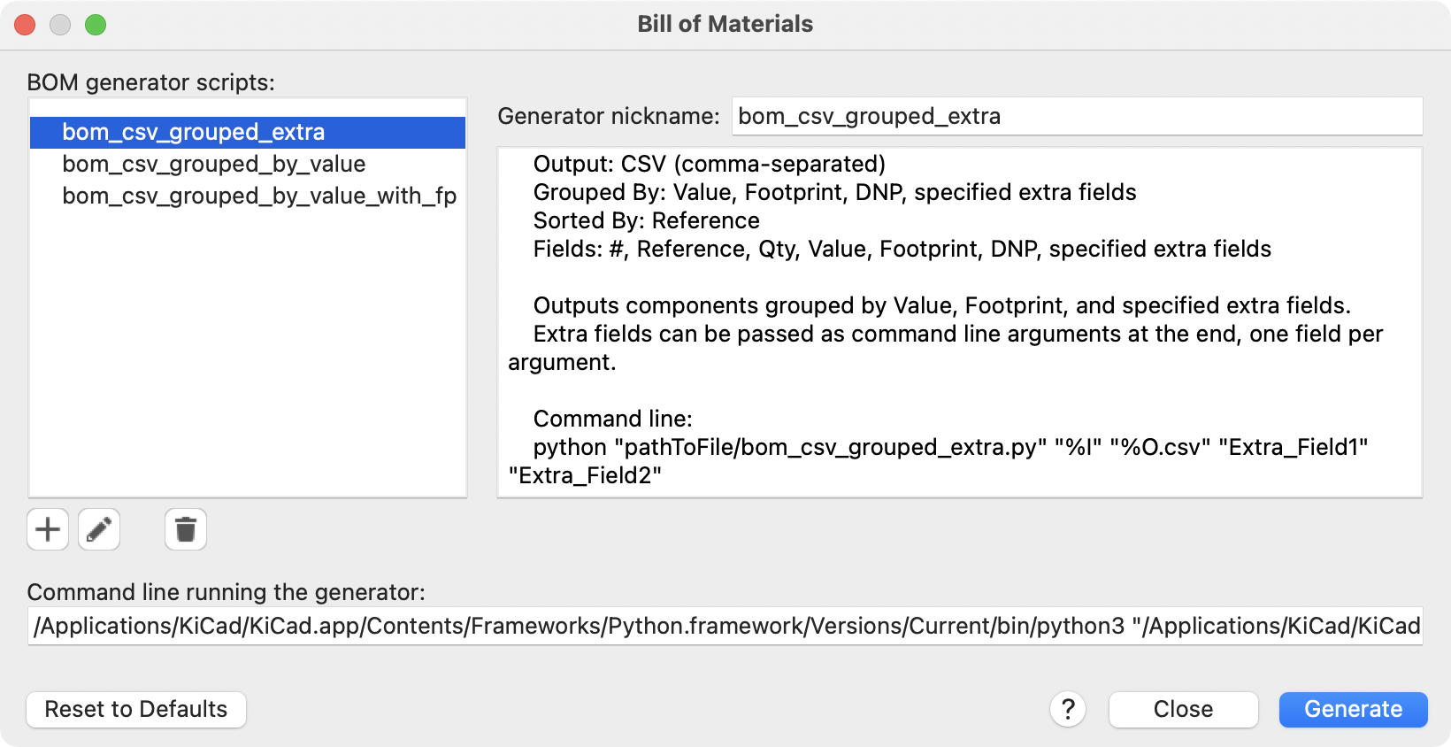
You can select which BOM generator to use in the BOM generator scripts list. The rest of the dialog displays information about the selected generator. You can change the displayed name of the generator with the Generator nickname textbox.
The pane at right displays information about the selected script. When the generator is executed, the right pane instead displays output from the script.
The text box at the bottom contains the command that KiCad will use to execute the generator. It is automatically populated when a script is selected, but the command may need to be hand-edited for some generators. KiCad saves the command line for each generator when the BOM tool is closed, so command line customizations are preserved. For more details about the command line, see the advanced documentation.
On Windows, the BOM Generator dialog has an additional option Show console window. When this option is unchecked, BOM generators run in a hidden console window and any output is redirected and printed in the dialog. When this option is checked, BOM generators run in a visible console window, which may be necessary if the generator plugin provides a graphical user interface.
BOM generator scripts
By default, the legacy BOM tool presents three output script options.
-
bom_csv_grouped_extraoutputs a CSV with a single section containing every component in the design. Components are grouped by value, footprint, DNP (do not populate), and any additional fields that are specified on the command line. To specify extra fields, add the desired field names as quoted strings at the end of the command line. For example, to include theMPNfield, the end of the command line would be:<path to script>/bom_csv_grouped_extra.py "%I" "%O.csv" "MPN". The columns in the BOM are:-
Line item number
-
Reference designator(s)
-
Quantity
-
Value
-
Footprint
-
DNP
-
Specified extra fields
-
-
bom_csv_grouped_by_valueoutputs a CSV with two sections. The first section contains every component in the design, with a single component on each line. The second section also contains every component, but components are grouped by symbol name, value, footprint, and DNP (do not populate). The columns in the BOM are:-
Line item number
-
Quantity
-
Reference designator(s)
-
Value
-
Symbol library and symbol name
-
Footprint
-
Datasheet
-
DNP
-
Any other symbol fields
-
-
bom_csv_grouped_by_value_with_fpoutputs a CSV with a single section containing every component in the design. Components are grouped by value, footprint, and DNP (do not populate). The columns in the BOM are:-
Reference designator(s)
-
Quantity
-
Value
-
Symbol name
-
Footprint
-
Symbol description
-
Vendor
-
DNP
-
Additional generator scripts are installed with KiCad but are not populated in the generator script list by default. The location of these scripts depends on the operating system and may vary based on installation location.
| Operating System | Location |
|---|---|
Windows |
|
Linux |
|
macOS |
|
Additional scripts can be added to the list of BOM generator scripts by clicking
the ![]() button. Scripts can be
removed by clicking the
button. Scripts can be
removed by clicking the ![]() button. The
button. The ![]() button opens the
selected script in a text editor.
button opens the
selected script in a text editor.
For more information on creating and using custom BOM generators, see the advanced documentation.
BOM export from PCB editor
The PCB Editor can export a BOM through File → Fabrication Outputs → BOM…. This method provides no control over the output format and does not include all symbol information, but is useful for PCB-only workflows that do not involve a schematic. In general, it is recommended to use the schematic editor’s BOM export tool instead.
Generating a Netlist
A netlist is a file which describes electrical connections between symbol pins. These connections are referred to as nets. Netlist files contain:
-
A list of symbols and their pins.
-
A list of connections (nets) between symbol pins.
Many different netlist formats exist. Sometimes the symbols list and the list of nets are two separate files. This netlist is fundamental in the use of schematic capture software, because the netlist is the link with other electronic CAD software, such as PCB layout software, simulators, and programmable logic compilers.
KiCad supports several netlist formats:
-
KiCad format, which can be imported by the KiCad PCB Editor. However, the "Update PCB from Schematic" tool should be used instead of importing a KiCad netlist into the PCB editor.
-
OrCAD PCB2 format, for designing PCBs with OrCAD.
-
Allegro format, for designing PCBs with Allegro.
-
PADS format, for designing PCBs with PADS.
-
CADSTAR format, for designing PCBs with CADSTAR.
-
Spice format, for use with various external circuit simulators.
| In KiCad version 5.0 and later, it is not necessary to create a netlist for transferring a design from the schematic editor to the PCB editor. Instead, use the "Update PCB from Schematic" tool. |
| Other software tools that use netlists may have restrictions on spaces and special characters in component names, pins, nets, and other fields. For compatibility, be aware of such restrictions in other tools you plan to use, and name components, nets, etc. accordingly. |
Netlist formats
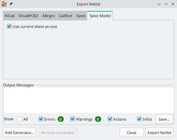
Netlists are exported with the Export Netlist dialog (File→Export→Netlist…).
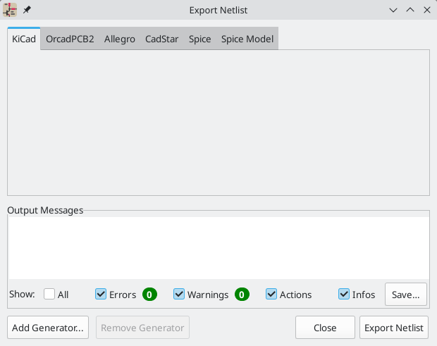
KiCad supports exporting netlists in several formats: KiCad, OrcadPCB2, Allegro, PADS, CADSTAR, Spice, and Spice Model. Each format can be selected by selecting the corresponding tab at the top of the window. Some netlist formats have additional options.
Clicking the Export Netlist button prompts for a netlist filename and saves the netlist.
| Netlist generation can take up to several minutes for large schematics. |
Custom generators for other netlist formats can be added by clicking the Add Generator… button. Custom generators are external tools that are called by KiCad, for example Python scripts or XSLT stylesheets. For more information on custom netlist generators, see the section on adding custom netlist generators.
Spice Netlist Format
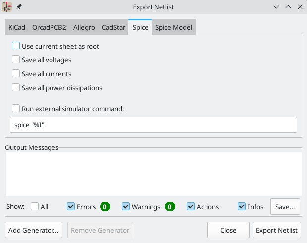
The Spice netlist format offers several options.
-
When the use current sheet as root is selected, only the current sheet is exported to a subcircuit model. Otherwise, the entire schematic sheet is exported.
-
The Save all voltages option adds a
.save allcommand to the netlist, which causes the simulator to save all node voltages. -
The Save all currents option adds a
.probe allicommand to the netlist, which causes the simulator save all node currents. -
The Save all power dissipations adds
.probecommands to save the power dissipation in each component. -
The Save all digital event data removes the
esave nonecommand from the netlist, which causes digital event data to be saved. Digital event data may consume a lot of memory.
| Exact behavior may vary between simulation tools. |
Passive symbol values are automatically adjusted to be compatible with various Spice simulators. Specifically:
-
μandMas unit prefixes are replaced withuandMeg, respectively -
Units are removed (e.g.
4.7kΩis changed to4.7k) -
Values in RKM format are rewritten to be Spice-compatible (e.g.
4u7is changed to4.7u)
The Spice netlist exporter also provides an easy way to simulate the generated netlist with an external simulator. This can be useful for running a simulation without using KiCad’s internal ngspice simulator, or for running an ngspice simulation with options that are not supported by KiCad’s simulator tool.
Enter the path to the external simulator in the text box, with %I representing
the generated netlist. Check the run external simulator command box to
generate the netlist and automatically run the simulator.
The default simulator command (spice "%I") must be adjusted to point to
a simulator installed on your system.
|
Spice simulators expect simulation commands (.PROBE, .AC, .TRAN, etc.) to
be included in the netlist. Any text line included in the schematic diagram
starting with a period (.) will be included in the netlist. If a text object
contains multiple lines, only the lines beginning with a period will be
included.
.include directives for including model library files are automatically
added to the netlist based on the Spice model settings for the symbols in
the schematic.
Spice Model Netlist Format
KiCad can also export a netlist of the schematic as a Spice subcircuit model, which can be included in a separate Spice simulation. Any hierarchical labels in the schematic are used as pins for the subcircuit model. Each pin in the model is annotated with a comment describing the pin’s electrical direction:
-
Inputhierarchical labels are mapped to aninputannotation -
Outputhierarchical labels are mapped to anoutputannotation -
Bidirectionalhierarchical labels are mapped to aninoutannotation -
Tri-statehierarchical labels are mapped to atristateannotation -
Passivehierarchical labels are mapped to apassiveannotation
When the use current sheet as root is selected, only the current sheet is exported to a subcircuit model. Otherwise, the entire schematic sheet is exported.
Netlist examples
Below is the schematic from the sallen_key project included in KiCad’s
simulation demos.
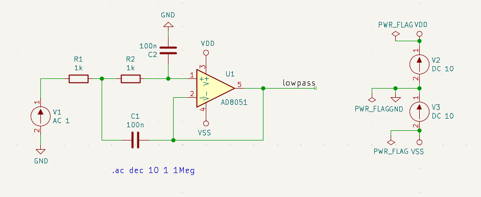
The KiCad format netlist for this schematic is as follows:
(export (version "E")
  (design
    (source "/usr/share/kicad/demos/simulation/sallen_key/sallen_key.kicad_sch")
    (date "Sun 01 May 2022 03:14:05 PM EDT")
    (tool "Eeschema (6.0.4)")
    (sheet (number "1") (name "/") (tstamps "/")
      (title_block
        (title)
        (company)
        (rev)
        (date)
        (source "sallen_key.kicad_sch")
        (comment (number "1") (value ""))
        (comment (number "2") (value ""))
        (comment (number "3") (value ""))
        (comment (number "4") (value ""))
        (comment (number "5") (value ""))
        (comment (number "6") (value ""))
        (comment (number "7") (value ""))
        (comment (number "8") (value ""))
        (comment (number "9") (value "")))))
  (components
    (comp (ref "C1")
      (value "100n")
      (libsource (lib "sallen_key_schlib") (part "C") (description ""))
      (property (name "Sheetname") (value ""))
      (property (name "Sheetfile") (value "sallen_key.kicad_sch"))
      (sheetpath (names "/") (tstamps "/"))
      (tstamps "00000000-0000-0000-0000-00005789077d"))
    (comp (ref "C2")
      (value "100n")
      (fields
        (field (name "Fieldname") "Value")
        (field (name "SpiceMapping") "1 2")
        (field (name "Spice_Primitive") "C"))
      (libsource (lib "sallen_key_schlib") (part "C") (description ""))
      (property (name "Fieldname") (value "Value"))
      (property (name "Spice_Primitive") (value "C"))
      (property (name "SpiceMapping") (value "1 2"))
      (property (name "Sheetname") (value ""))
      (property (name "Sheetfile") (value "sallen_key.kicad_sch"))
      (sheetpath (names "/") (tstamps "/"))
      (tstamps "00000000-0000-0000-0000-00005789085b"))
    (comp (ref "R1")
      (value "1k")
      (fields
        (field (name "Fieldname") "Value")
        (field (name "SpiceMapping") "1 2")
        (field (name "Spice_Primitive") "R"))
      (libsource (lib "sallen_key_schlib") (part "R") (description ""))
      (property (name "Fieldname") (value "Value"))
      (property (name "SpiceMapping") (value "1 2"))
      (property (name "Spice_Primitive") (value "R"))
      (property (name "Sheetname") (value ""))
      (property (name "Sheetfile") (value "sallen_key.kicad_sch"))
      (sheetpath (names "/") (tstamps "/"))
      (tstamps "00000000-0000-0000-0000-0000578906ff"))
    (comp (ref "R2")
      (value "1k")
      (fields
        (field (name "Fieldname") "Value")
        (field (name "SpiceMapping") "1 2")
        (field (name "Spice_Primitive") "R"))
      (libsource (lib "sallen_key_schlib") (part "R") (description ""))
      (property (name "Fieldname") (value "Value"))
      (property (name "SpiceMapping") (value "1 2"))
      (property (name "Spice_Primitive") (value "R"))
      (property (name "Sheetname") (value ""))
      (property (name "Sheetfile") (value "sallen_key.kicad_sch"))
      (sheetpath (names "/") (tstamps "/"))
      (tstamps "00000000-0000-0000-0000-000057890691"))
    (comp (ref "U1")
      (value "AD8051")
      (fields
        (field (name "Spice_Lib_File") "ad8051.lib")
        (field (name "Spice_Model") "AD8051")
        (field (name "Spice_Netlist_Enabled") "Y")
        (field (name "Spice_Primitive") "X"))
      (libsource (lib "sallen_key_schlib") (part "Generic_Opamp") (description ""))
      (property (name "Spice_Primitive") (value "X"))
      (property (name "Spice_Model") (value "AD8051"))
      (property (name "Spice_Lib_File") (value "ad8051.lib"))
      (property (name "Spice_Netlist_Enabled") (value "Y"))
      (property (name "Sheetname") (value ""))
      (property (name "Sheetfile") (value "sallen_key.kicad_sch"))
      (sheetpath (names "/") (tstamps "/"))
      (tstamps "00000000-0000-0000-0000-00005788ff9f"))
    (comp (ref "V1")
      (value "AC 1")
      (libsource (lib "sallen_key_schlib") (part "VSOURCE") (description ""))
      (property (name "Sheetname") (value ""))
      (property (name "Sheetfile") (value "sallen_key.kicad_sch"))
      (sheetpath (names "/") (tstamps "/"))
      (tstamps "00000000-0000-0000-0000-000057336052"))
    (comp (ref "V2")
      (value "DC 10")
      (fields
        (field (name "Fieldname") "Value")
        (field (name "Spice_Node_Sequence") "1 2")
        (field (name "Spice_Primitive") "V"))
      (libsource (lib "sallen_key_schlib") (part "VSOURCE") (description ""))
      (property (name "Fieldname") (value "Value"))
      (property (name "Spice_Primitive") (value "V"))
      (property (name "Spice_Node_Sequence") (value "1 2"))
      (property (name "Sheetname") (value ""))
      (property (name "Sheetfile") (value "sallen_key.kicad_sch"))
      (sheetpath (names "/") (tstamps "/"))
      (tstamps "00000000-0000-0000-0000-0000578900ba"))
    (comp (ref "V3")
      (value "DC 10")
      (fields
        (field (name "Fieldname") "Value")
        (field (name "Spice_Node_Sequence") "1 2")
        (field (name "Spice_Primitive") "V"))
      (libsource (lib "sallen_key_schlib") (part "VSOURCE") (description ""))
      (property (name "Fieldname") (value "Value"))
      (property (name "Spice_Primitive") (value "V"))
      (property (name "Spice_Node_Sequence") (value "1 2"))
      (property (name "Sheetname") (value ""))
      (property (name "Sheetfile") (value "sallen_key.kicad_sch"))
      (sheetpath (names "/") (tstamps "/"))
      (tstamps "00000000-0000-0000-0000-000057890232")))
  (libparts
    (libpart (lib "sallen_key_schlib") (part "C")
      (footprints
        (fp "C?")
        (fp "C_????_*")
        (fp "C_????")
        (fp "SMD*_c")
        (fp "Capacitor*"))
      (fields
        (field (name "Reference") "C")
        (field (name "Value") "C"))
      (pins
        (pin (num "1") (name "") (type "passive"))
        (pin (num "2") (name "") (type "passive"))))
    (libpart (lib "sallen_key_schlib") (part "Generic_Opamp")
      (fields
        (field (name "Reference") "U")
        (field (name "Value") "Generic_Opamp"))
      (pins
        (pin (num "1") (name "+") (type "input"))
        (pin (num "2") (name "-") (type "input"))
        (pin (num "3") (name "V+") (type "power_in"))
        (pin (num "4") (name "V-") (type "power_in"))
        (pin (num "5") (name "") (type "output"))))
    (libpart (lib "sallen_key_schlib") (part "R")
      (footprints
        (fp "R_*")
        (fp "Resistor_*"))
      (fields
        (field (name "Reference") "R")
        (field (name "Value") "R"))
      (pins
        (pin (num "1") (name "") (type "passive"))
        (pin (num "2") (name "") (type "passive"))))
    (libpart (lib "sallen_key_schlib") (part "VSOURCE")
      (fields
        (field (name "Reference") "V")
        (field (name "Value") "VSOURCE")
        (field (name "Fieldname") "Value")
        (field (name "Spice_Primitive") "V")
        (field (name "Spice_Node_Sequence") "1 2"))
      (pins
        (pin (num "1") (name "") (type "input"))
        (pin (num "2") (name "") (type "input")))))
  (libraries
    (library (logical "sallen_key_schlib")
      (uri "/usr/share/kicad/demos/simulation/sallen_key/sallen_key_schlib.kicad_sym")))
  (nets
    (net (code "1") (name "/lowpass")
      (node (ref "C1") (pin "1") (pintype "passive"))
      (node (ref "U1") (pin "2") (pinfunction "-") (pintype "input"))
      (node (ref "U1") (pin "5") (pintype "output")))
    (net (code "2") (name "GND")
      (node (ref "C2") (pin "2") (pintype "passive"))
      (node (ref "V1") (pin "2") (pintype "input"))
      (node (ref "V2") (pin "2") (pintype "input"))
      (node (ref "V3") (pin "1") (pintype "input")))
    (net (code "3") (name "Net-(C1-Pad2)")
      (node (ref "C1") (pin "2") (pintype "passive"))
      (node (ref "R1") (pin "1") (pintype "passive"))
      (node (ref "R2") (pin "2") (pintype "passive")))
    (net (code "4") (name "Net-(C2-Pad1)")
      (node (ref "C2") (pin "1") (pintype "passive"))
      (node (ref "R2") (pin "1") (pintype "passive"))
      (node (ref "U1") (pin "1") (pinfunction "+") (pintype "input")))
    (net (code "5") (name "Net-(R1-Pad2)")
      (node (ref "R1") (pin "2") (pintype "passive"))
      (node (ref "V1") (pin "1") (pintype "input")))
    (net (code "6") (name "VDD")
      (node (ref "U1") (pin "3") (pinfunction "V+") (pintype "power_in"))
      (node (ref "V2") (pin "1") (pintype "input")))
    (net (code "7") (name "VSS")
      (node (ref "U1") (pin "4") (pinfunction "V-") (pintype "power_in"))
      (node (ref "V3") (pin "2") (pintype "input")))))
In Spice format, the netlist is as follows:
.title KiCad schematic
.include "ad8051.lib"
XU1 Net-_C2-Pad1_ /lowpass VDD VSS /lowpass AD8051
C2 Net-_C2-Pad1_ GND 100n
C1 /lowpass Net-_C1-Pad2_ 100n
R2 Net-_C2-Pad1_ Net-_C1-Pad2_ 1k
R1 Net-_C1-Pad2_ Net-_R1-Pad2_ 1k
V1 Net-_R1-Pad2_ GND AC 1
V2 VDD GND DC 10
V3 GND VSS DC 10
.ac dec 10 1 1Meg
.end