Symbols and Symbol Libraries
KiCad organizes symbols into symbol libraries, which hold collections of symbols. Each symbol in a schematic is uniquely identified by a full name that is composed of a library nickname and a symbol name. For example, the identifier Audio:AD1853 refers to the AD1853 symbol in the Audio library.
Managing symbol libraries
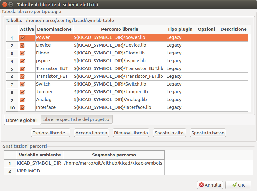
KiCad uses a table of symbol libraries to map a symbol library nickname to an underlying symbol library on disk. Kicad uses a global symbol library table as well as a table specific to each project. To edit either symbol library table, use Preferences → Manage Symbol Libraries….
La tabella delle librerie simboli globali contiene l’elenco delle librerie sempre disponibili indipendentemente dal progetto attualmente caricato. La tabella viene salvata nel file sym-lib-table nella cartella di configurazione di KiCad. La posizione di questa cartella dipende dal sistema operativo utilizzato.
La tabella della libreria dei simboli specifica del progetto contiene l’elenco delle librerie che sono disponibili specificamente per il progetto attualmente caricato. Se sono presenti librerie di simboli specifiche del progetto, la tabella viene salvata nel file sym-lib-table nella cartella del progetto.
Configurazione iniziale
The first time the KiCad Schematic Editor is run and the global symbol table file sym-lib-table is not found in the KiCad configuration folder, KiCad will guide the user through setting up a new symbol library table. This process is described above.
Gestione voci della tabella
Symbol libraries can only be used if they have been added to either the global or project-specific symbol library table.
Aggiungere una libreria facendo clic sul pulsante ![]() selezionando una libreria o facendo clic sul pulsante
selezionando una libreria o facendo clic sul pulsante ![]() e digitando il percorso di un file di libreria . La libreria selezionata verrà aggiunta alla tabella della libreria attualmente aperta (globale o specifica del progetto). Le librerie possono venir rimosse selezionando le voci della libreria desiderate e facendo clic sul pulsante
e digitando il percorso di un file di libreria . La libreria selezionata verrà aggiunta alla tabella della libreria attualmente aperta (globale o specifica del progetto). Le librerie possono venir rimosse selezionando le voci della libreria desiderate e facendo clic sul pulsante ![]() .
.
The ![]() and
and ![]() buttons move the selected library up and down in the library table. This does not affect the display order of libraries in the Symbol Library Browser, Symbol Editor, or Add Symbol tool.
buttons move the selected library up and down in the library table. This does not affect the display order of libraries in the Symbol Library Browser, Symbol Editor, or Add Symbol tool.
Libraries can be made inactive by unchecking the Active checkbox in the first column. Inactive libraries are still in the library table but do not appear in any library browsers and are not loaded from disk, which can reduce loading times.
A range of libraries can be selected by clicking the first library in the range and then Shift-clicking the last library in the range.
Each library must have a unique nickname: duplicate library nicknames are not allowed in the same table. However, nicknames can be duplicated between the global and project library tables. Libraries in the project table take precedence over libraries with the same name in the global table.
Gli identificatori di libreria non devono essere correlati al nome file o al percorso della libreria. Il carattere due punti (:) non può essere utilizzato negli identificatori di libreria o nei nomi dei simboli perché viene utilizzato come separatore tra identificatori e simboli.
Each library entry must have a valid path. Paths can be defined as absolute, relative, or by environment variable substitution.
The appropriate library format must be selected in order for the library to be properly read. "KiCad" format is used for KiCad version 6+ libraries (.kicad_sym files), while "Legacy" format is used for libraries from older versions of KiCad (.lib files). Legacy libraries are read-only, but can be migrated to KiCad format libraries using the Migrate Libraries button (see section Migrating Legacy Libraries).
Esiste un campo optionale per la descrizione della voce di libreria. Il campo opzioni non viene usato al momento perciò aggiungere opzioni non ha alcun effetto sul caricamento delle librerie.
Sostituzione delle variabili ambiente
Le tabelle delle librerie di simboli supportano la sostituzione delle variabili ambiente, che consente di definire variabili ambiente contenenti percorsi personalizzati in cui sono archiviate le librerie. La sostituzione delle variabili ambiente è supportata usando la sintassi ${ENV_VAR_NAME} nel percorso della libreria dei simboli.
By default, KiCad defines several environment variables which are described in the project manager documentation. Environment variables can be configured in the Preferences → Configure Paths… dialog.
Using environment variables in the symbol library tables allows libraries to be relocated without breaking the symbol library tables, so long as the environment variables are updated when the library location changes.
${KIPRJMOD} is a special environment variable that always expands to the absolute path of the current project directory. ${KIPRJMOD} allows libraries to be stored in the project folder without having to use an absolute path in the project library table. This makes it possible to relocate projects without breaking their project library tables.
Modelli di utilizzo
Le librerie di simboli si possono definire sia globalmente che specificatamente al progetto correntemente caricato. Le librerie di simboli definite nella tabella globale dell’utente sono sempre disponibili e vengono memorizzate nel file sym-lib-table nella cartella di configurazione di KiCad dell’utente. La tabella delle librerie di simboli specifica del progetto è attiva solamente per il file progetto aperto al momento.
Ci sono vantaggi e svantaggi per ogni metodo. Definire tutte le librerie nella tabella globale significa che queste saranno sempre disponibili alla bisogna. Lo svantaggio di ciò è aumenterà che il tempo di caricamento.
Definire tutte le librerie di simboli su base specifica del progetto significa che si avranno solamente le librerie necessarie per quel progetto e ciò diminuirà il tempo di caricamento dei simboli. Lo svantaggio è che sarà sempre necessario ricordarsi di aggiungere ogni libreria di simboli necessaria per ogni progetto.
Uno schema di utilizzo potrebbe essere quello di definire le librerie di uso comune a livello globale e le librerie richieste solo per il progetto nella tabella della libreria specifica del progetto.
Migrazione delle librerie obsolete
Legacy libraries (.lib files) are read-only, but they can be migrated to KiCad version 6 libraries (.kicad_sym). KiCad version 6 libraries cannot be viewed or edited by KiCad versions older than 6.0.0.
Legacy libraries can be converted to KiCad 6 libraries by selecting them in the symbol library table and clicking the Migrate Libraries button. Multiple libraries can be selected and migrated at once by Ctrl-clicking or shift-clicking.
Libraries can also be converted one at a time by opening them in the Symbol Editor and saving them as a new library.
Rimappatura dei vecchi progetti
Quando si carica uno schema creato prima dell’implementazione della tabella delle librerie di simboli, KiCad cercherà di rimappare i collegamenti alle librerie di simboli presenti nello schema ai simboli nella tabella librerie appropriati. Il successo di questo processo dipende da diversi fattori:
-
le librerie originali usate nello schema sono ancora disponibili e invariate da quando il simbolo è stato aggiunto allo schema.
-
tutte le operazioni di salvataggio sono state eseguite quando sono state rilevate per creare una libreria di salvataggio o mantenere aggiornata la libreria di salvataggio esistente.
-
l’integrità della libreria cache dei simboli del progetto non è stata danneggiata.
|
La rimappatura eseguirà un salvataggio di tutti i file che vengono modificati durante l’operazione, nella cartella di salvataggio all’interno della cartella del progetto. Effettuare sempre un salvataggio del progetto prima di rimappare, (N.d.T. per evitare brutte sorprese) nel caso in cui qualcosa vada storto. |
|
L’operazione di recupero viene eseguita anche se è stata disabilitata per garantire che i simboli corretti siano disponibili per la rimappatura. Non annullare questa operazione o la rimappatura non riuscirà a rimappare correttamente i simboli degli schemi. Eventuali collegamenti a simboli spezzati dovranno essere corretti manualmente. |
|
Se le librerie originali sono state rimosse e il recupero non è stato eseguito, la cache della libreria può essere utilizzata come libreria di ripristino come ultima risorsa. Copiare la libreria della cache in un nuovo nome file e aggiungere il nuovo file della libreria all’inizio dell’elenco delle librerie usando una versione di KiCad precedente all’implementazione della tabella della libreria dei simboli. |
Creating and editing symbols
Overview of symbols and symbol libraries
A symbol is a schematic representation of a component. A symbol is composed of:
-
Elementi grafici (linee, cerchi, archi, testo, ecc.) che determinano l’aspetto del simbolo nello schema elettrico.
-
Pins, which have both graphic properties (line, clock, inverted, low level active, etc.) and electrical properties (input, output, bidirectional, etc.) used by the Electrical Rules Check (ERC) tool.
-
Fields, such as references, values, corresponding footprint names for PCB design, etc.
Una libreria di simboli è composta da uno o più simboli. Generalmente i simboli sono raggruppati per funzione, tipo e/o produttore.
I simboli possono essere derivati da un altro simbolo nella stessa libreria. I simboli derivati condividono la forma grafica e le definizioni dei pin del simbolo di base, ma possono sovrascrivere i campi delle proprietà del simbolo di base (valore, impronta, filtri impronta, documentazione, descrizione, ecc.). I simboli derivati possono essere utilizzati per definire simboli simili ad una parte di base. Ad esempio, i simboli 74LS00, 74HC00 e 7437 potrebbero essere tutti derivati da un simbolo 7400. Nelle versioni precedenti di KiCad, i simboli derivati erano chiamati alias.
Symbol Editor overview
KiCad provides a symbol editing tool that allows you to create libraries, add, delete or transfer symbols between libraries, export symbols to files, and import symbols from files.
In general, the flow for designing a symbol involves:
-
Specificare se il simbolo è formato da più di un’unità.
-
Specificare se il simbolo possiede uno stile corpo alternativo (altrimenti detto rappresentazione De Morgan).
-
La progettazione della sua rappresentazione simbolica usando linee, rettangoli, cerchi, poligoni e testo.
-
Adding pins by carefully defining each pin’s graphical elements, name, number, and electrical property (input, output, tri-state, power output, etc.).
-
Determining if the symbol should be derived from another symbol with the same graphical design and pin definition.
-
L’aggiunta di campi opzionali come il nome dell’impronta usata dal software di progettazione di circuiti stampati e/o la definizione della loro visibilità.
-
La documentazione del simbolo aggiungendo una stringa di descrizione, collegamenti ai datasheet, ecc.
-
Il salvataggio nella libreria scelta.
The Symbol Editor main window is shown below. It consists of three toolbars for quick access to common features and a symbol viewing/editing area. Not all commands are available on the toolbars, but all commands are available in the menus.
Barra strumenti principale
The main toolbar is at the top of the main window. It has buttons for the undo/redo commands, zoom commands, symbol properties dialogs, and unit/representation management controls.
|
Create a new symbol in the selected library. |
|
Save the currently selected library. All modified symbols in the library will be saved. |
|
Undo last edit. |
|
Redo last undo. |
|
Refresh display. |
|
Zoom in. |
|
Zoom out. |
|
Zoom to fit symbol in display. |
|
Zoom to fit selection. |
|
Rotate counter-clockwise. |
|
Rotate clockwise. |
|
Mirror horizontally. |
|
Mirror vertically. |
|
Edit the current symbol properties. |
|
Edit the symbol’s pins in a tabular interface. |
|
Open the symbol’s datasheet, if it is defined. |
|
Test the current symbol for design errors. |
|
Select the normal body style. The button is disabled if the current symbol does not have an alternate body style. |
|
Select the alternate body style. The button is disabled if the current symbol does not have an alternate body style. |
|
Select the unit of a multi-unit symbol to display. The drop down control will be disabled if the current symbol is not derived from a symbol with multiple units. |
|
Enable synchronized pins edit mode. When this mode is enabled, any pin modifications are propagated to all other symbol units. Pin number changes are not propagated. This mode is automatically enabled for symbols with multiple interchangeable units and cannot be enabled for symbols with only one unit. |
|
Insert current symbol into the schematic. |
Barra strumenti elementi
La barra strumenti verticale sul lato destro della finestra principale permette di piazzare tutti gli elementi richiesti per progettare un simbolo.
|
Select tool. Right-clicking with the select tool opens the context menu for the object under the cursor. Left-clicking with the select tool displays the attributes of the object under the cursor in the message panel at the bottom of the main window. Double-left-clicking with the select tool will open the properties dialog for the object under the cursor. |
|
Pin tool. Left-click to add a new pin. |
|
Graphical text tool. Left-click to add a new graphical text item. |
|
Graphical textbox tool. Left-click to add a new graphical textbox item. |
|
Rectangle tool. Left-click to begin drawing the first corner of a graphical rectangle. Left-click again to place the opposite corner of the rectangle. |
|
Circle tool. Left-click to begin drawing a new graphical circle from the center. Left-click again to define the radius of the circle. |
|
Arc tool. Left-click to begin drawing a new graphical arc item from the first arc end point. Left-click again to define the second arc end point. Adjust the radius by dragging the arc center point. |
|
Connected line tool. Left-click to begin drawing a new graphical line item in the current symbol. Left-click for each additional connected line. Double-left-click to complete the line. |
|
Anchor tool. Left-click to set the anchor position of the symbol. |
|
Delete tool. Left-click to delete an object from the current symbol. |
Barra opzioni
La barra strumenti verticale, posizionata sul lato sinistro della finestra principale, permette di impostare alcune opzioni di disegno dell’editor.
|
Toggle grid visibility on and off. |
|
Set units to inches. |
|
Set units to mils (0.001 inch). |
|
Set units to millimeters. |
|
Toggle full screen cursor on and off. |
|
Toggle display of pin electrical types. |
|
Toggle display of library and symbol tree. |
Saving symbols to libraries
The ![]() button displays or hides the list of available libraries, which allows you to select an active library. When a symbol is saved, it will be placed in this library.
button displays or hides the list of available libraries, which allows you to select an active library. When a symbol is saved, it will be placed in this library.
Clicking the ![]() icon on the left toolbar toggles the treeview of libraries and symbols. Clicking on a symbol opens that symbol.
icon on the left toolbar toggles the treeview of libraries and symbols. Clicking on a symbol opens that symbol.
| Alcuni simboli sono derivati da altri simboli. I nomi dei simboli derivati vengono visualizzati in corsivo nella vista ad albero. Se un simbolo derivato viene aperto, la sua grafica non sarà modificabile. I suoi campi simbolo invece saranno modificabili normalmente. Per modificare la grafica di un simbolo base e di tutti i suoi simboli derivati, bisogna aprire il simbolo base. |
Dopo la modifica, un simbolo può essere salvato nella libreria corrente o in una nuova libreria.
Per salvare il simbolo modificato nella libreria corrente, fare clic sull’icona ![]() . Le modifiche verranno scritte sul simbolo esistente.
. Le modifiche verranno scritte sul simbolo esistente.
| Saving a modified symbol also saves all other modified symbols in the same library. |
Per salvare i cambiamenti del simbolo in un nuovo simbolo, fare clic su File → Salva con nome…. Il simbolo può essere salvato nella libreria corrente o in una diversa libreria. Si può impostare anche un nuovo nome per il simbolo.
Per creare un nuovo file contenente solo il simbolo corrente, fare clic su File → Esporta → Simbolo…. Questo file sarà un file di libreria standard che conterrà solo un simbolo.
Creating symbols
Creating a new symbol
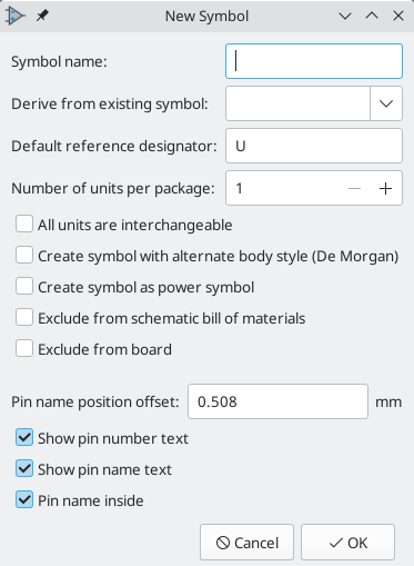
Un nuovo simbolo può essere creato facendo clic sull’icona ![]() . Verranno richieste un certo numero di proprietà del simbolo.
. Verranno richieste un certo numero di proprietà del simbolo.
-
A symbol name
-
An optional base symbol to derive the new symbol from. The new symbol will use the base symbol’s graphical shape and pin configuration, but other symbol information can be modified in the derived symbol. The base symbol must be in the same library as the new derived symbol.
-
Il prefisso del riferimento (
U,C,R…). -
The number of units per package, and whether those units are interchangeable (for example a 7400 quad NAND symbol could have 4 units, one for each gate).
-
If an alternate body style (sometimes referred to as a "De Morgan equivalent") is desired.
-
Whether the symbol is a power symbol. Power symbols appear in the Add Power Symbol dialog in the Schematic editor, their
Valuefields are not editable in the schematic, they cannot be assigned a footprint, they are not added to the PCB, and they are not included in the bill of materials. -
Whether the symbol should be excluded from the bill of materials.
-
Whether the symbol should be excluded from the PCB.
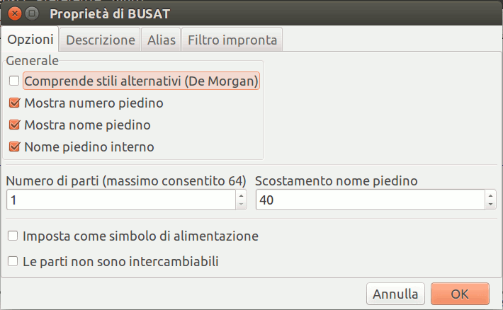
There are also several graphical options.
-
The offset between the end of each pin and its pin name.
-
Whether the pin number and pin name should be displayed.
-
Whether the pin names should be displayed alongside the pins or at the ends of the pins inside the symbol body.
These properties can also be changed later in the Symbol Properties window.
Un nuovo simbolo verrà creato usando le proprietà sopraesposte e apparirà nell’editor come mostrato sotto.
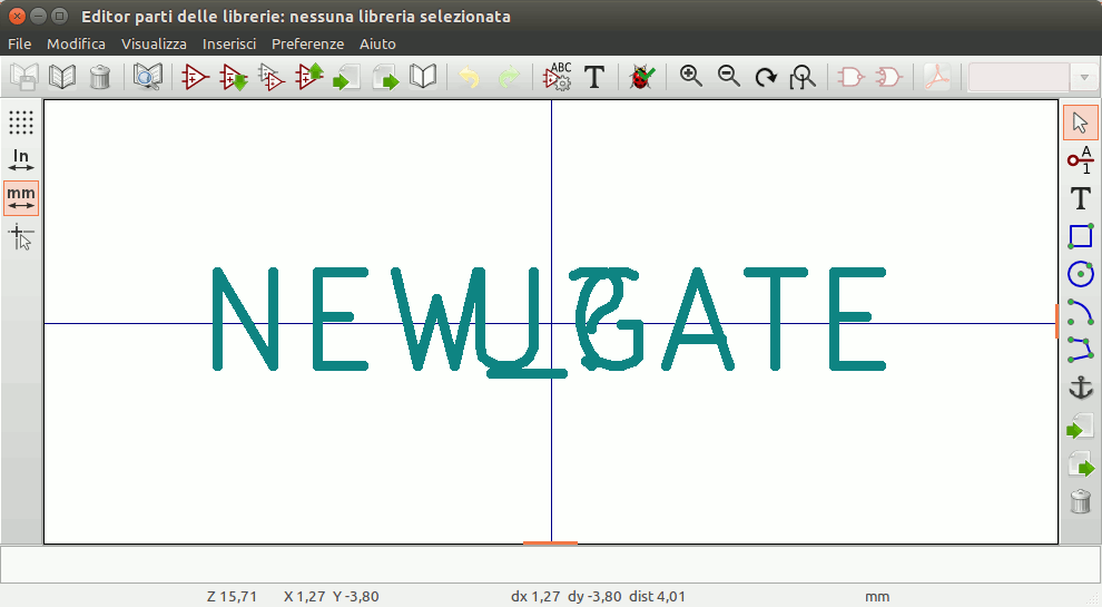
The blue cross in the center is the symbol anchor, which specifies the symbol origin i.e. the coordinates (0, 0). The anchor can be repositioned by selecting the ![]() icon and clicking on the new desired anchor position.
icon and clicking on the new desired anchor position.
Creating a symbol from another symbol
Spesso, il simbolo che si vuole creare è simile ad un altro già presente in una libreria componenti. In questo caso risulta più facile caricare e modificare un simbolo esistente (N.d.T. piuttosto che ricrearne uno nuovo da zero).
-
Caricare il simbolo che verrà usato come punto di partenza.
-
Save a new copy of the symbol using File → Save As…. The Save As dialog will prompt for a name for the new symbol and the library to save it in.
-
Modifica il nuovo simbolo come richiesto.
-
Salva il simbolo modificato.
Proprietà del simbolo
Symbol properties are set when the symbol is created but they can be modified at any point. To change the symbol properties, click on the ![]() button to show the Symbol Properties dialog. You can also double click an empty spot in the editing canvas.
button to show the Symbol Properties dialog. You can also double click an empty spot in the editing canvas.
It is important to set the number of units and check all units are interchangeable and has alternate body style, as applicable, because these settings affect how pins and graphics are added to each symbol unit.
If you change the number of units per package after adding the pins to the symbol, you will need to do extra work to add pins and graphics for the additional units. The pins and graphics would have been automatically added to each unit had these properties been correctly set initially. Nevertheless, it is possible to modify these properties at any time.
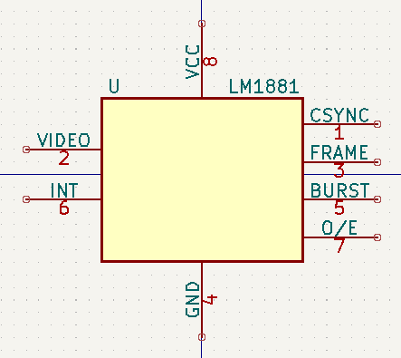
The graphic options Show pin number and Show pin name define the visibility of the pin number and pin name text. The option Place pin names inside defines the pin name position relative to the pin body. The pin names will be displayed inside the symbol outline if the option is checked. In this case the Pin Name Position Offset property defines the shift of the text away from the body end of the pin. A value from 0.02 to 0.05 inches is usually reasonable.
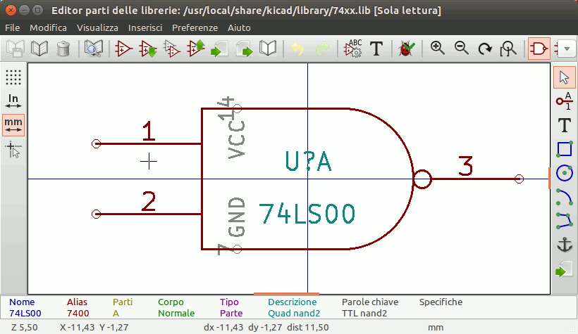
The example below shows a symbol with the Place pin name inside option unchecked. Notice the position of the names and pin numbers.
Symbol Name, Description, and Keywords
Symbol name is the symbol’s name in the library. Symbols are identified by a combination of the library and symbol name.
In previous versions of KiCad, the symbol name was linked to the Value field. This link is removed in KiCad 7.0 and later.
The symbol description should contain a brief description of the component, such as the component function, distinguishing features, and package options. The keywords should contain additional terms related to the component. Keywords are used primarily to assist in searching for the symbol.
A symbol’s name, description, and keywords are all used when searching for symbols in the Symbol Editor and Add a Symbol dialog. The description and keywords are displayed in the Symbol Library Browser and Add a Symbol dialog.
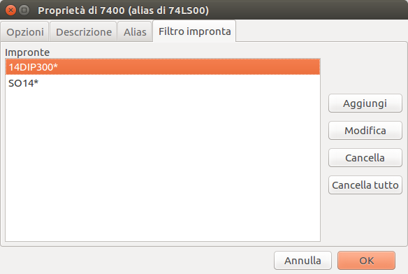
Footprint Filters
The footprint filters tab is used to define which footprints are appropriate to use with the symbol. The filters can be applied in the Footprint Assignment tool so that only appropriate footprints are displayed for each symbol.
Multiple footprint filters can be defined. Footprints that match any of the filters will be displayed; if no filters are defined, then all footprints will be displayed.
Filters can use wildcards: * matches any number of characters, including zero, and ? matches zero or one characters. For example, SOIC-* would match the SOIC-8_3.9x4.9mm_P1.27mm footprint as well as any other footprint beginning with SOIC-. The filter SOT?23 matches SOT23 as well as SOT-23.
Definizione piedini per simboli multipli e rappresentazioni simboliche alternative
Se il simbolo possiede uno stile corpo alternativo definito, sarà necessario selezionarne uno alla volta per la modifica. Per modificare la rappresentazione normale, fare clic su ![]() .
.
To edit the alternate representation, click on the ![]() icon. Use the
icon. Use the  unit selection dropdown to select the unit you wish to edit.
Elementi grafici
Gli elementi grafici formano la rappresentazione di un simbolo e non contengono informazioni di connessioni elettriche. Vengono creati usando i seguenti strumenti:
-
Linee e poligoni definiti da punti di inizio e fine.
-
Rettangoli definiti da due angoli diagonali.
-
Cerchi definiti da centro e raggio.
-
Archi definiti da punti di inizio e fine dell’arco ed il suo centro. Un arco va da 0° a 180°.
La barra strumenti verticale sul lato destro della finestra principale permette di piazzare tutti gli elementi grafici richiesti per progettare la rappresentazione di un simbolo.
Appartenenza di elementi grafici
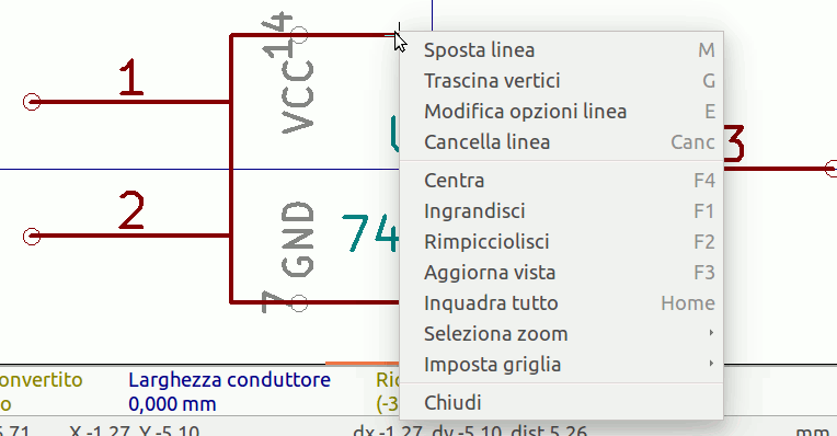
Ogni elemento grafico (linea, arco, cerchio, ecc.) può essere definito come comune a tutte le unità e/o stili di corpi o specifico di una data unità e/o stile corpo. Le opzioni dell’elemento sono accessibili facilmente facendo clic destro sull’elemento per mostrare il menu contestuale per l’elemento selezionato. Di seguito è mostrato il menu contestuale per un elemento linea.
Si può anche fare doppio clic sinistro su un elemento per modificare le sue proprietà. Di seguito viene mostrata la finestra di dialogo delle proprietà di un elemento poligono.
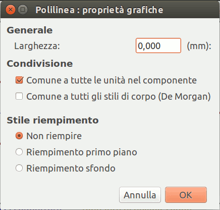
Le proprietà di un elemento grafico sono:
-
Border determines whether the the shape’s outline should be drawn.
-
Width and color define the line width and color of the border. A border width of
0uses the schematic’s default symbol line width. Style determines the line style of the border (solid, dashed, dotted, etc.). -
Fill Style determines if the shape defined by the graphical element is to be drawn unfilled or filled. The fill color can be the color theme’s body outline color, body background color, or a custom color.
-
Common to all units in symbol determines if the graphical element is drawn for each unit in symbol with more than one unit per package or if the graphical element is only drawn for the current unit.
-
Common to all body styles (De Morgan) determines if the graphical element is drawn for each symbolic representation in symbols with an alternate body style or if the graphical element is only drawn for the current body style.
-
Private to Symbol Editor causes the shape to be visible only when the symbol is edited in the Symbol Editor. The shape will be hidden when the symbol is added to a schematic.
Elementi di testo grafico
![]() permette la creazione di testo grafico. Il testo grafico viene automaticamente orientato per essere leggibile, anche se il simbolo viene reso speculare. Si noti che gli elementi di testo grafico non sono campi del simbolo.
permette la creazione di testo grafico. Il testo grafico viene automaticamente orientato per essere leggibile, anche se il simbolo viene reso speculare. Si noti che gli elementi di testo grafico non sono campi del simbolo.
Unità multiple per simbolo e stili di corpo alternativi
I simboli possono avere fino a due rappresentazioni simboliche (una standard e una alternativa, spesso chiamata "equivalente DeMorgan") e/o avere più di una unità per contenitore (per esempio le porte logiche). Alcuni simboli possono avere più di una unità per ogni contenitore con simboli e configurazioni di piedinatura differenti.
For example, consider a relay with two switches, which can be designed as a symbol with three different units: a coil, switch 1, and switch 2. Designing a symbol with multiple units per package and/or alternate body styles is very flexible. A pin or a body symbol item can be common to all units or specific to a given unit or they can be common to both symbolic representation so are specific to a given symbol representation.
By default, pins are specific to a unit and body style. When a pin is common to all units or all body styles, it only needs to be created once. This is also the case for the body style graphic shapes and text, which may be common to each unit, but typically are specific to each body style.
To add additional units to a symbol, set the Number of Units property to the appropriate number in the Symbol Properties dialog. By default, symbol units are named Unit A, Unit B, etc., but you can set an arbitrary name for the current unit using Edit → Set Unit Display Name….
To add an alternate body style, set the Has alternate body style (De Morgan) property in the Symbol Properties dialog.
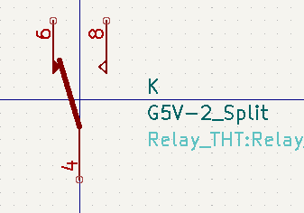
Esempio di simbolo multiunità non interscambiabili
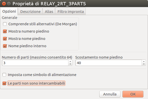
Come esempio di simbolo con più unità non intercambiabili, si consideri un relè con 3 unità per contenitore: una bobina, l’interruttore 1 e l’interruttore 2.
The three units are not all the same, so All units are interchangeable should be deselected in the Symbol Properties dialog. Alternatively, this option could have been specified when the symbol was initially created.
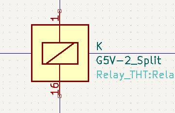
Unit A
Unit B
Unit C
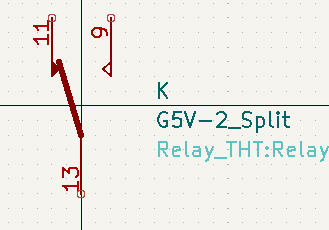
L’unità A non ha lo stesso simbolo e disposizione di pin delle unità B e C, perciò le unità non sono intercambiabili.
|
Synchronized Pins Edit Mode can be enabled by clicking the
|
Creazione e modifica di piedini
You can create and insert a pin by clicking on the ![]() button. Pin properties can be edited by double clicking on the pin. You can also delete or move pins that you have already added. Pins must be created carefully, because any error will have consequences on the PCB design.
button. Pin properties can be edited by double clicking on the pin. You can also delete or move pins that you have already added. Pins must be created carefully, because any error will have consequences on the PCB design.
Panoramica piedino
A pin is defined by its graphical representation, its name, and its number. The pin’s name and number can contain letters, numbers, and symbols, but not spaces. For the Electrical Rules Check (ERC) tool to be useful, the pin’s electrical type (input, output, tri-state…) must also be defined correctly. If this type is not defined properly, the schematic ERC check results may be invalid.
Note importanti:
-
Symbol pins are matched to footprint pads by number. The pin number in the symbol must match the corresponding pad number in the footprint.
-
Do not use spaces in pin names and numbers. Spaces will be automatically replaced with underscores (
_). -
To define a pin name with an inverted signal (overbar) use the
~(tilde) character followed by the text to invert in braces. For example~{FO}Owould display FO O. -
Se il nome pin è vuoto, il pin viene considerato senza nome.
-
I nomi di pin possono essere ripetuti in un simbolo.
-
I numeri di pin devono essere univoci in un simbolo.
Proprietà piedino
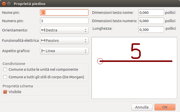
La finestra di dialogo delle proprietà del pin permette di modificare tutte le caratteristiche di un pin. Questa finestra di dialogo salta fuori automaticamente quando si crea un pin o facendo doppio clic su un pin già esistente. Questa finestra di dialogo permette di modificare:
-
Nome e dimensione testo del pin.
-
Numero e dimensione testo del pin.
-
Lunghezza pin.
-
Tipo elettrico e stile grafico del piedino.
-
Unità e appartenenza a rappresentazioni alternative.
-
Visibilità pin.
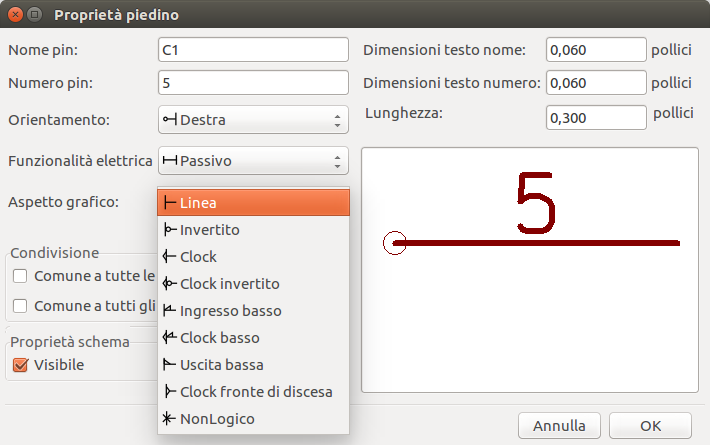
Stili grafici pin
The different pin graphic styles are shown in the figure below. These styles are purely graphical and do not affect the pin’s electrical type.
Tipi elettrici del pin
Each pin in a symbol has an electrical type, such as input, output, or tri-state.
Choosing the correct electrical type is important for the schematic ERC tool. ERC will check that pins are connected appropriately, for example ensuring that input pins are driven and power inputs receive power from an appropriate source.
You can use the Pin Conflicts Map in the schematic editor to configure which pin types are allowed to connect and which will conflict. The default Pin Conflicts settings are briefly explained below. For more information, see the ERC documentation.
Additionally, some pin types have special behavior outside of ERC: in the router, pads corresponding to a free pin can be connected to copper of any other net without causing a DRC error, and pads corresponding to stacked unconnected pins do not need to be connected to each other.
Pin Type |
Description |
Input |
A pin which is exclusively an input. The default Pin Conflicts settings allow input pins to connect to most other types of pin. |
Output |
A pin which is exclusively an output. The default Pin Conflicts settings allow output pins to connect to most types of pin that aren’t also outputs. |
Bidirectional |
A pin that can be either an input or an output, such as a microcontroller data bus pin. The default Pin Conflicts settings allow bidirectional pins to connect to most other types of pins, though there are a few more restrictions than with input pins. |
Tri-state |
A three state output pin (high, low, or high impedance). The default Pin Conflicts settings allow tri-state pins to connect to most other types of pins, but warnings are generated when they are connected to most types of output or power pins. |
Passive |
A pin that is not connected to active electronics, for example pins on a resistor or connector. The default Pin Conflicts settings allow passive pins to connect to most other types of pin. |
Free |
A pin that does not electrically affect the operation of the device. These pins typically represent package leads that are not internally connected to the chip. The default Pin Conflicts settings allow free pins to connect to most other types of pin. In the PCB editor, pads corresponding to free pins can be connected to copper of any other net without causing a DRC error. |
Unspecified |
A pin which has an unspecified type. With the default Pin Conflicts settings, ERC generates warnings when unspecified pins are connected to most other types of pins. |
Power input |
A pin that powers the device. The default Pin Conflicts settings allow power input pins to connect to most other pin types. However, power input pins that are not connected to a power output pin generate an ERC violation. Additionally, power input pins that are marked invisible are automatically connected to the net with the same name as the pin. See the Power Symbols section for more information. |
Power output |
A pin that provides power to other pins, such as a regulator output. The default Pin Conflicts settings allow power output pins to connect to most types of output pins, but not input pins. |
Open collector |
An open collector logic output. The default Pin Conflicts settings allow open collector pins to connect to most input pins and other open collector pins, but not to most other types of outputs. |
Open emitter |
An open emitter logic output. The default Pin Conflicts settings allow open collector pins to connect to most input pins and other open emitter pins, but not to most other types of outputs. |
Unconnected |
A pin that should not be connected to anything. The default Pin Conflict settings do not allow pins of type unconnected to connect to any other type of pin, and ERC will not generate an "unconnected pin" violation when pins of this type are left unconnected. If a footprint has multiple pads corresponding to a single unconnected pin, the pads do not need to be connected to each other in the board. When multiple pins of type unconnected are stacked in a symbol, they are connected to separate nets, whereas stacked pins of other types are connected to the same net. Note that this pin type is different than placing a no connect flag on a pin in the schematic. The unconnected pin type indicates that the pin should never be connected in any schematic, while a no connect flag indicates that the pin is intentionally unconnected in the current schematic. |
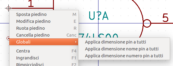
Pushing Pin Properties to Other Pins
You can apply the length, name size, or number size of a pin to the other pins in the symbol by right clicking the pin and selecting Push Pin Length, Push Pin Name Size, or Push Pin Number Size, respectively. All other pins in the symbol will be updated.
Definizione piedini per componenti multipli e rappresentazioni simboliche alternative
I simboli con più unità e/o rappresentazioni grafiche sono particolarmente problematici durante la creazione e la modifica dei pin. La maggior parte dei pin è specifica per ciascuna unità di simbolo (perché ogni unità ha un diverso set di pin) e per ogni stile del corpo (perché la forma e la posizione sono diverse tra lo stile del corpo normale e la forma alternativa).
L’editor della libreria dei simboli consente la creazione simultanea di pin. Per impostazione predefinita, le modifiche apportate a un pin vengono apportate per tutte le unità di un simbolo a più unità e ad entrambe le rappresentazioni per i simboli con una rappresentazione simbolica alternativa. L’unica eccezione è il tipo grafico e il nome del pin, che rimangono scollegati tra le unità dei simboli e gli stili del corpo. Questa dipendenza è stata stabilita per consentire una più facile creazione e modifica dei pin nella maggioranza dei casi. Questa dipendenza può essere disabilitata attivando l’icona ![]() sulla barra degli strumenti principale. Ciò consentirà di creare pin per ogni unità e rappresentazione in modo completamente indipendente.
sulla barra degli strumenti principale. Ciò consentirà di creare pin per ogni unità e rappresentazione in modo completamente indipendente.
I pin possono essere comuni o specifici per diverse unità. I pin possono anche essere comuni a entrambe le rappresentazioni simboliche o specifici di ciascuna rappresentazione simbolica. Quando un pin è comune a tutte le unità, deve essere disegnato solo una volta. I pin sono impostati come comuni o specifici nella finestra di dialogo delle proprietà dei pin.
An example is the output pin in the 7400 quad dual input NAND gate. Since there are four units and two symbolic representations, there are eight separate output pins defined in the symbol definition. When creating a new 7400 symbol, unit A of the normal symbolic representation will be shown in the library editor. To edit the pin style in the alternate symbolic representation, it must first be enabled by clicking the ![]() button on the tool bar. To edit the pin number for each unit, select the appropriate unit using the drop down control.
button on the tool bar. To edit the pin number for each unit, select the appropriate unit using the drop down control.
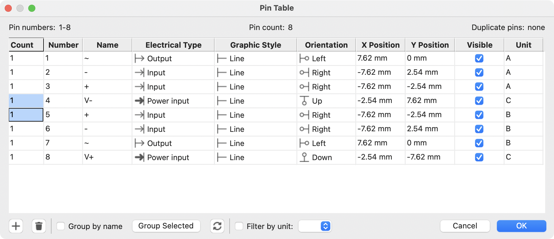
Tabella pin
Un altro modo per modificare i pin è usando la tabella pin, che è accessibile tramite l’icona ![]() . La tabella pin mostra tutti i pin nel simbolo e le relative proprietà in una vista tabellare, quindi è utile per apportare modifiche in blocco ai pin.
. La tabella pin mostra tutti i pin nel simbolo e le relative proprietà in una vista tabellare, quindi è utile per apportare modifiche in blocco ai pin.
Qualsiasi proprietà del pin può essere modificata facendo clic sulla cella appropriata. I pin possono essere aggiunti e rimossi rispettivamente con le icone ![]() e
e ![]() .
.
You can edit the same property for multiple pins simultaneously by grouping pins. Pins can be automatically grouped by name, or you manually group several pins by selecting them and clicking Group Selected. Click the ![]() button to clear the manual grouping. You can also filter the table to only display pins in certain units.
button to clear the manual grouping. You can also filter the table to only display pins in certain units.
| Le colonne della tabella pin possono essere visualizzate o nascoste facendo clic con il pulsante destro del mouse sulla riga dell’intestazione e selezionando o deselezionando le colonne aggiuntive. Alcune colonne sono nascoste per impostazione predefinita. |
Lo screenshot qui sotto mostra la tabella pin per un operazionale quadruplo.
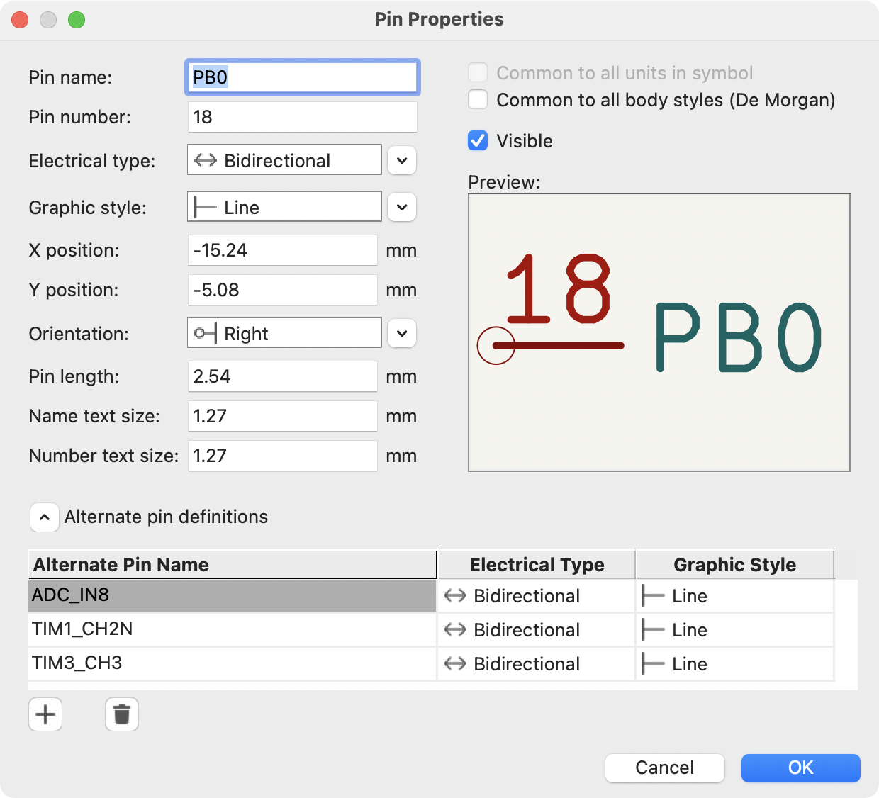
Definizioni alternative dei pin
Ai pin possono essere aggiunte definizioni alternative. Le definizioni di pin alternative consentono ad un utente di selezionare un nome, un tipo elettrico e uno stile grafico diversi per pin, quando il simbolo viene posizionato sullo schema. Tutto ciò può essere utile per i pin che hanno più funzioni, come i pin di un microcontrollore.
Le definizioni di pin alternative vengono aggiunte con finestra di dialogo Proprietà pin come mostrato di seguito. Ogni definizione alternativa contiene un nome pin, un tipo elettrico e uno stile grafico. Questo pin di microcontrollore ha tutte le sue funzioni periferiche definite nel simbolo come nomi di pin alternativi.
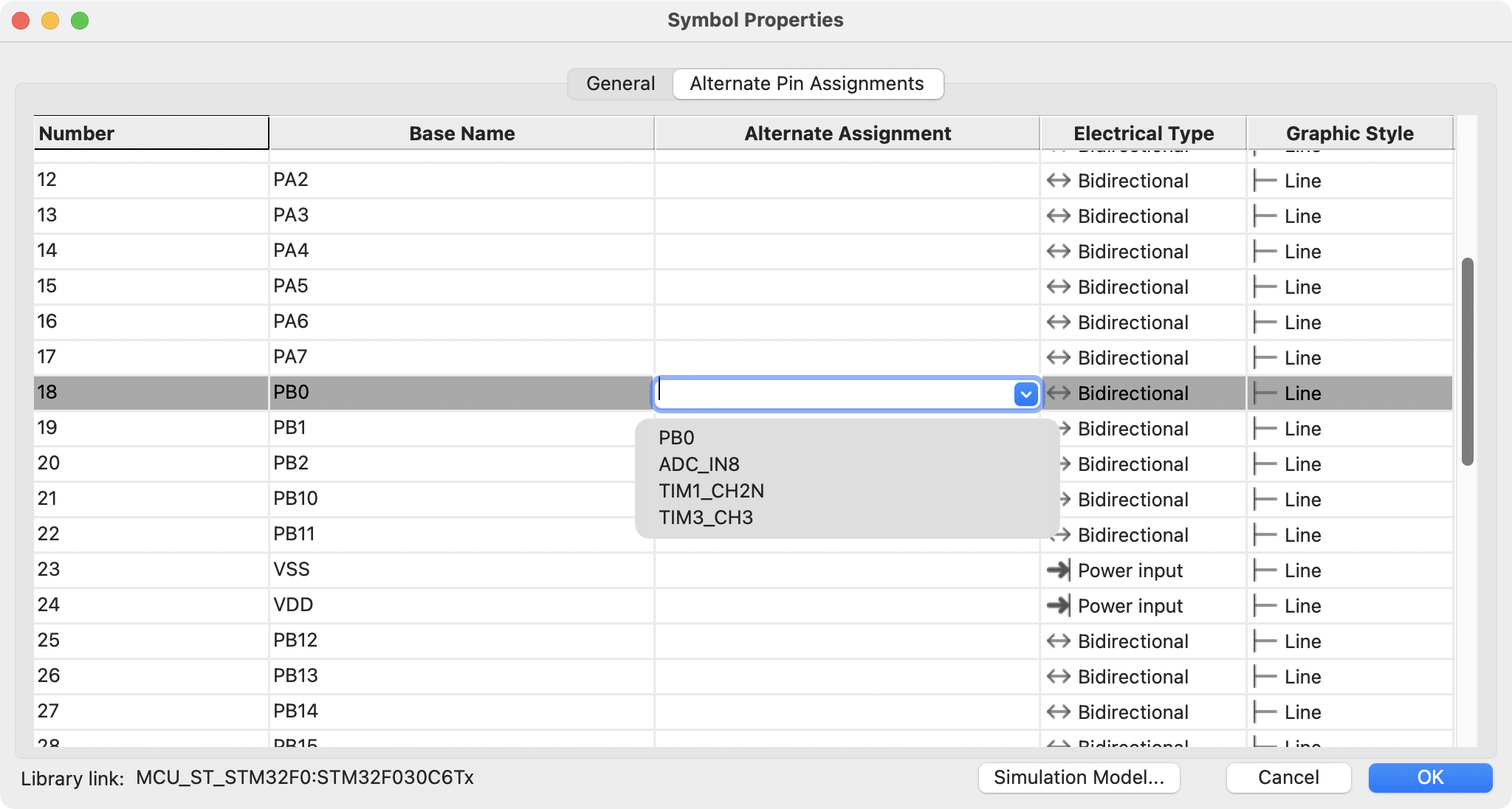
Le definizioni di pin alternative vengono selezionate nell’editor degli schemi una volta che il simbolo sia stato inserito nello schema. Il pin alternativo viene assegnato nella scheda Assegnazioni pin alternativi della finestra di dialogo Proprietà simbolo. Le definizioni alternative sono selezionabili nell’elenco a discesa nella colonna Assegnazione alternativa.
Campi del simbolo
All library symbols are defined with four default fields. The reference designator, value, footprint assignment, and datasheet link fields are created whenever a symbol is created or copied. Only the reference designator is required.
The Footprint field, if used, contains a reference to a footprint for the symbol. The format is LIBNAME:FOOTPRINTNAME, where LIBNAME is the name of the footprint library in the footprint library table (see the Footprint Library Table section in the PCB Editor manual) and FOOTPRINTNAME is the name of the footprint in the library LIBNAME.
I simboli definiti nelle librerie sono in genere definiti solo con questi quattro campi predefiniti. Campi aggiuntivi come fornitore, numero di parte, costo unitario, ecc. possono essere aggiunti ai simboli della libreria, ma generalmente questo viene fatto nell’editor dello schema in modo che i campi aggiuntivi possano essere applicati a tutti i simboli nello schema.
| A convenient way to create additional empty symbol fields is to use define field name templates. Field name templates define empty fields that are added to each symbol when it is inserted into the schematic. Field name templates can be defined globally (for all schematics) in the Schematic Editor Preferences, or they can be defined locally (specific to each project) in the Schematic Setup dialog. |
| If you want to manage a large amount of component data in symbol fields, consider using database libraries. |
Modifica campi del simbolo
To edit an existing symbol field, double-click the field, select it or hover and press E, or right-click on the field text and select Properties….
Per aggiungere nuovi campi, eliminare campi facoltativi o modificare campi esistenti, utilizzare l’icona ![]() sulla barra degli strumenti principale per aprire la finestra di dialogo Proprietà simbolo.
sulla barra degli strumenti principale per aprire la finestra di dialogo Proprietà simbolo.
Fields are text information associated with the symbol. Do not confuse them with text in the graphic representation of a symbol.
Creating Power Symbols
Power symbols are symbols that are used to label a wire as part of a global power net, like VCC or GND. The behavior of power symbols is described in the electrical connections section. Power symbols are handled and created the same way as normal symbols, but there are several additional considerations described below.
It may be useful to place power symbols in a dedicated library. KiCad’s symbol library places power symbols in the power library, and users may create libraries to store their own power symbols. If the Define as power symbol box is checked in a symbol’s properties, that symbol will appear in the Schematic Editor’s Add Power Symbol dialog for convenient access.
Di seguito è riportato un esempio di simbolo di potenza GND.
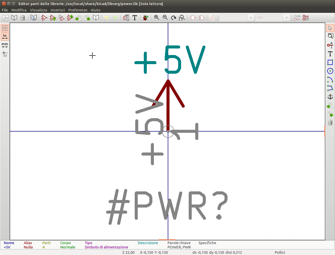
Power symbols consist of a pin of type "Power input" that is marked invisible. They must also have the Define as power symbol property checked. Invisible power input pins have a special property of making implicit global connections based on the pin name.
| If the power symbol has the Define as power symbol property checked, the power input pin does not need to be marked invisible. However, the convention is to make these pins invisible anyway. |
Per creare un simbolo di potenza, seguire questi passi:
-
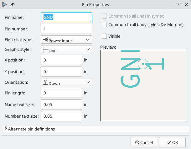
Add a pin of type Power input, with Visible unchecked, and the pin named according to the desired net. Make the pin number
1, the length0, and set the graphic style to Line. The pin name establishes the connection to the net; in this case the pin will automatically connect to the netGND. The pin number, length, and line style do not matter electrically. -
Posiziona il pin sull’ancora del simbolo.
-
Usa gli strumenti forma per disegnare la grafica del simbolo.
-
Set the symbol value. The symbol value does not matter electrically, but it is displayed in the schematic. To eliminate confusion, it should match the pin name (which determines the connected net name).
-
Check the Define as power symbol box in Symbol Properties window. This makes the symbol appear in the Add Power Symbol dialog, makes the
Valuefield read-only in the schematic, prevents the symbol from being assigned a footprint, and excludes the symbol from the board, BOM, and netlists. -
Set the symbol reference and uncheck the Show box. The reference text is not important except for the first character, which should be
#. For the power symbol shown above, the reference could be#GND. Symbols with references that begin with#are not added to the PCB, are not included in Bill of Materials exports or netlists, and they cannot be assigned a footprint in the footprint assignment tool. If a power symbol’s reference does not begin with#, the character will be inserted automatically when the annotation or footprint assignment tools are run.
An easier method to create a new power symbol is to use another symbol as a starting point, as described earlier.
| The connected net name is determined by the power symbol’s pin name, not the name or value of the symbol. When modifying an existing power symbol, make sure to rename the pin so that the new symbol connects to the appropriate power net. This means that power symbol net names can only be changed in the symbol editor, not in the schematic. |
Checking Symbols
The Symbol Editor can check for common issues in your symbols. Run the symbol checker using the ![]() button in the top toolbar.
button in the top toolbar.
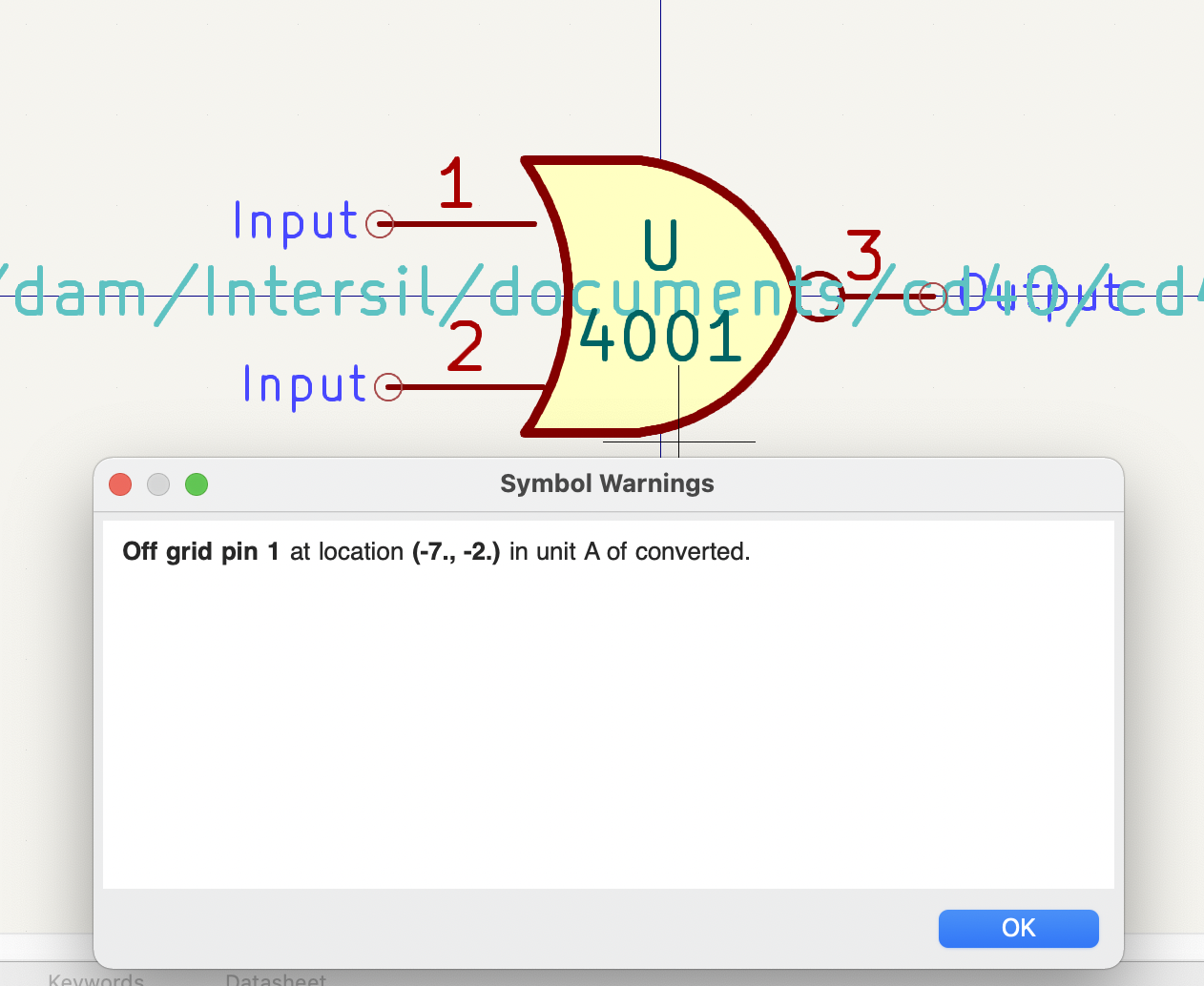
The symbol checker checks for:
-
Pins that are off-grid
-
Pins that are duplicated between symbol units
-
Incorrectly designed power symbols. Power symbols should have:
-
A single unit
-
No alternate body styles
-
A single pin which is either of type Power Output (see PWR_FLAG) or invisible and of type Power Input (see power symbols)
-
-
Illegal reference designator prefixes: reference designator prefixes should not end with a number or
? -
Hidden Power Input pins in non-power symbols: these create implicit connections and are not recommended
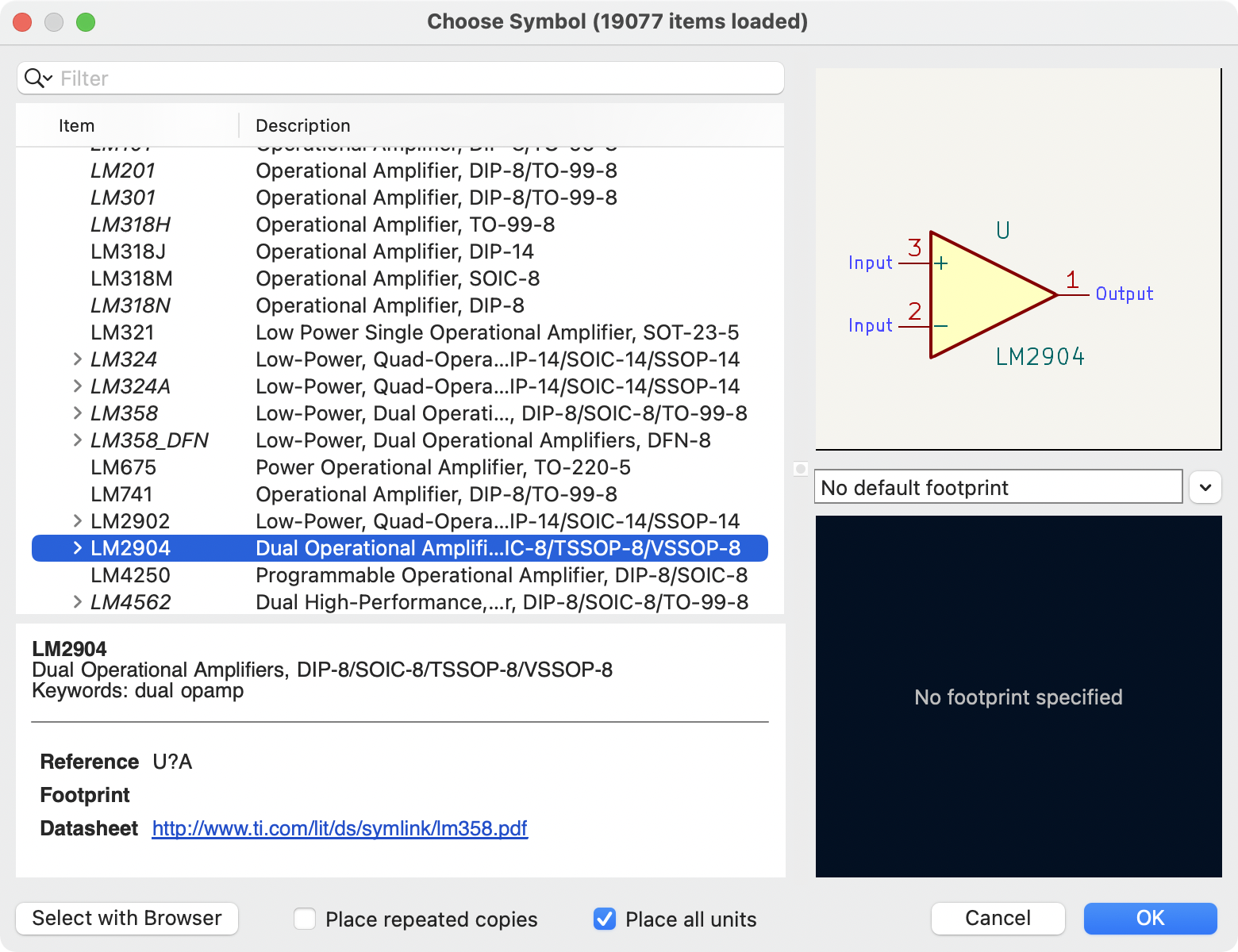
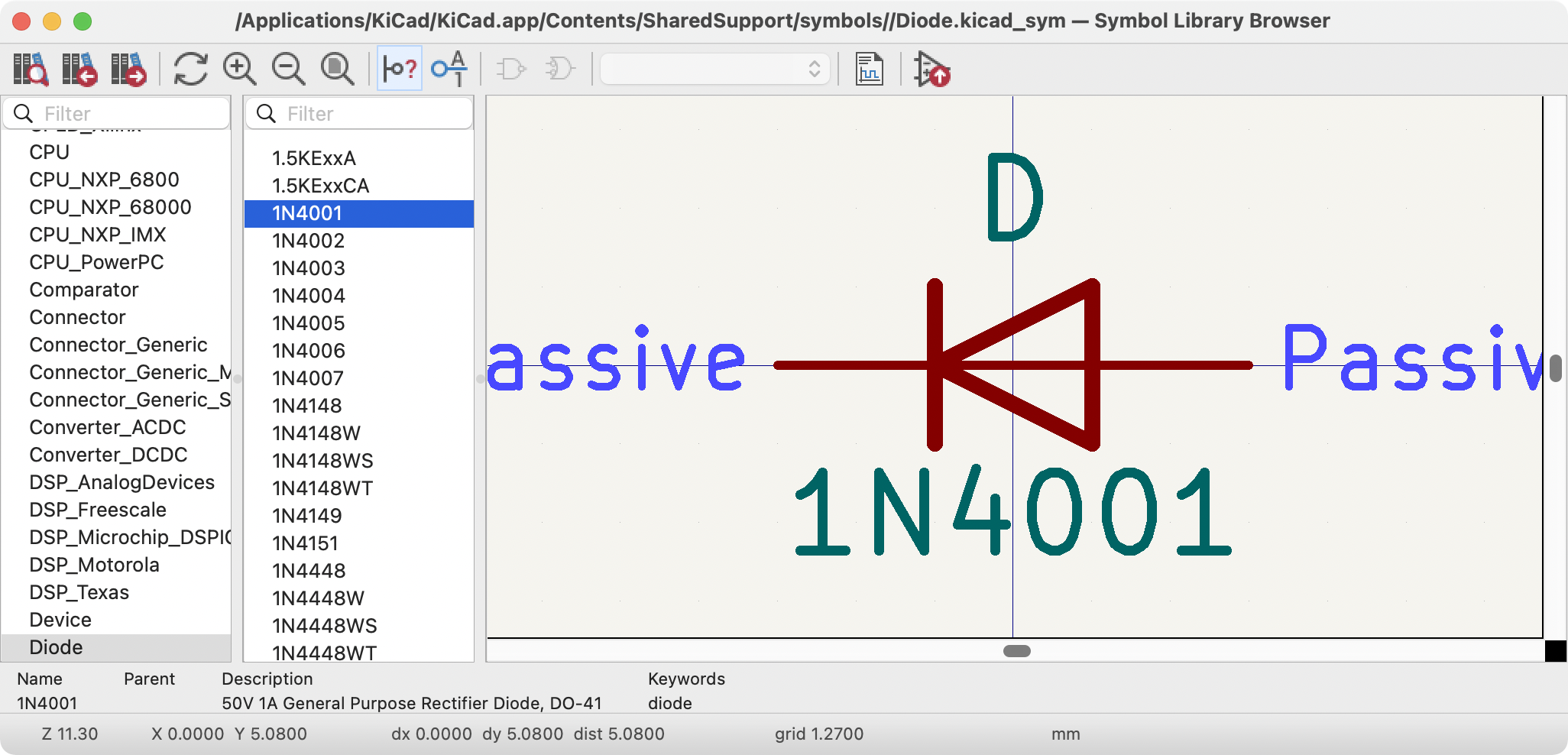
Browsing symbol libraries
The Symbol Library Browser allows you to quickly examine the contents of symbol libraries. The Symbol Library Viewer can be accessed by clicking ![]() icon on the main toolbar, View → Symbol Library Browser, or clicking Select With Browser in the Choose Symbol window.
icon on the main toolbar, View → Symbol Library Browser, or clicking Select With Browser in the Choose Symbol window.
To examine the contents of a library, select a library from the list on the left hand pane. All symbols in the selected library will appear in the second pane. Select a symbol name to view the symbol.
Facendo doppio clic sul nome di un simbolo o utilizzando il pulsante ![]() si aggiunge il simbolo allo schema.
si aggiunge il simbolo allo schema.
La barra superiore contiene i seguenti comandi:
|
Open the selected symbol in the Choose Symbol window. |
|
Select previous symbol in library. |
|
Select next symbol in library. |
|
Zoom tools. |
|
Select standard or alternate De Morgan representation of symbol, if applicable. |
|
Select the unit of a multi-unit symbol. |
|
Open the symbol’s datasheet, if it is defined. |
|
Insert current symbol into the schematic. |